Automatic burning machine for camera module group measurement

A camera module and burner technology, which is applied in image communication, television, electrical components, etc., can solve the problems of increasing hidden troubles, increasing production costs, and increasing the number of equipment, so as to improve test efficiency and reduce floor space , reducing the effect of the operator

Pending Publication Date: 2020-12-29
NINGBO SUNNY OPOTECH CO LTD
View PDF4 Cites 0 Cited by
  • Summary
  • Abstract
  • Description
  • Claims
  • Application Information

AI Technical Summary

Problems solved by technology

However, the degree of parallelization of the existing rotary test equipment needs to be further improved
For example, the loading and unloading process is difficult to execute well in parallel with the testing process
For another example, the test boxes located in four directions of the rotary test equipment all need to be connected with wires to complete the power-on test, but as the rotary test equipment continues to rotate, these wires may be entangled and pulled each other, causing the rotary test equipment to fail. Do not reset after working for a period of time (i.e. rotate in the opposite direction to release the entangled wire)
The above problems not only increase the hidden danger of failure, but also reduce the production efficiency (because the test work cannot be carried out during the reset process)
For another example, in the existing rotary testing equipment, it is necessary to install the camera module or the carrier equipped with the camera module on the transferable panel in advance, and this process needs to be completed manually or by using another special equipment
As mentioned above, manual operation has low work efficiency, high labor intensity, and there are problems such as unstable work quality
Using another special equipment to install the camera module or the carrier equipped with the camera module on the transferable panel will increase the number of equipment, resulting in an increase in occupied area, a decrease in output per unit area, and an increase in production costs, etc. question

Method used


Image

  • Automatic burning machine for camera module group measurement
  • Automatic burning machine for camera module group measurement
  • Automatic burning machine for camera module group measurement

Examples


Embodiment Construction

[0046] For a better understanding of the application, various aspects of the application will be described in more detail with reference to the accompanying drawings. It should be understood that these detailed descriptions are descriptions of exemplary embodiments of the application only, and are not intended to limit the scope of the application in any way. Throughout the specification, the same reference numerals refer to the same elements. The expression "and / or" includes any and all combinations of one or more of the associated listed items.

[0047] It should be noted that in this specification, expressions of first, second, etc. are only used to distinguish one feature from another, and do not represent any limitation on the features. Accordingly, a first body discussed hereinafter may also be referred to as a second body without departing from the teachings of the present application.

[0048] In the drawings, the thickness, size and shape of objects have been slight...


PUM


Abstract

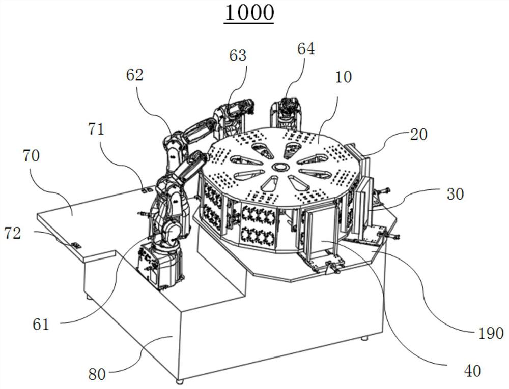
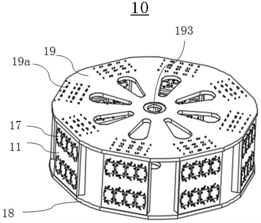
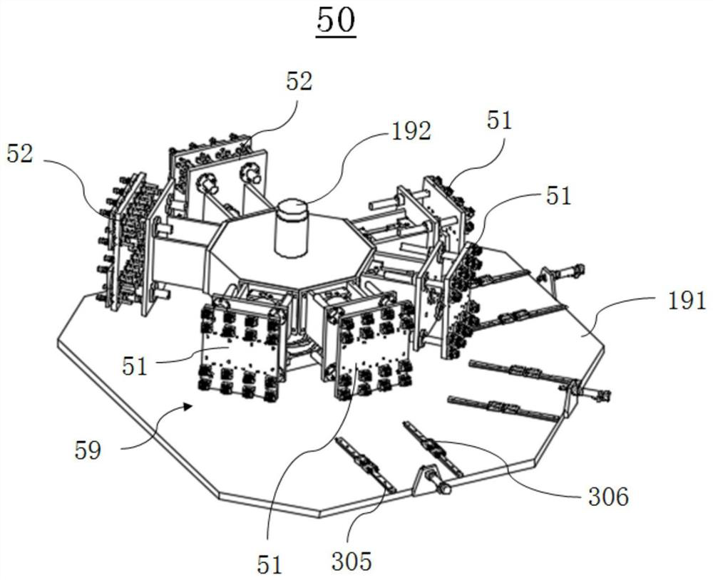
The invention relates to an automatic burning machine for camera module group measurement. The automatic burning machine comprises a hollow rotating body subassembly which comprises a rotating shaft and a plurality of carrier plates surrounding the rotating shaft to form an outer side wall, and the carrier plates can rotate around the rotating shaft; the automatic burning machine further comprisesa testing device subassembly which is located in the hollow rotating body subassembly and comprises a burning device, a plurality of testing devices and a plurality of probe mechanisms facing different directions, one or more mechanical arms which are used for loading and unloading carriers, a plurality of test light source subassemblies, and a control module which is used for controlling the mechanical arm to move a carrier carrying the unburned camera module and position the carrier on a carrier plate, controlling the unburned camera module on the carrier plate to be tested and burned, andcontrolling the mechanical arm to unload the carrier carrying the burnt camera module from the carrier plate. According to the automatic burning machine, the detection work of the burning process canbe decomposed into a plurality of sub-links which can be executed in parallel, so that the production efficiency is improved; and the automatic burning machine is compact in structure, and the outputrate of unit area can be improved.

Description

technical field [0001] The invention relates to the technical field of camera module assembly testing and automation, in particular, the invention relates to an automatic burner for camera module assembly testing. Background technique [0002] With the continuous improvement of the functions of smart products, the camera module has become one of the main components of the mobile terminal. The performance test of the camera module before installation is an important process to ensure the photography function of the subsequent mobile terminal. In this process, the camera module needs to be connected to external testing equipment through the module connector to complete performance testing and OTP programming (performance testing and OTP programming can sometimes be called camera module testing). In the prior art, it is usually necessary to detect parameters such as stained points, color, brightness uniformity, white balance, optical center, stripes, dark edges and RUCU on the ...

Claims


Application Information

Patent Timeline
Patent Type & Authority Applications(China)
IPC IPC(8): H04N17/00
CPCH04N17/002
Inventor 李振锋查方发蒋文斌
Owner NINGBO SUNNY OPOTECH CO LTD
Why Eureka
Try Eureka