Control system and control method of device for hyperthermic perfusion treatment

A technology of control system and treatment equipment, which is applied in the program control of sequence/logic controller, heating equipment for treatment treatment, cooling equipment for treatment treatment, etc., which can solve the problem of affecting the treatment effect and the easy occurrence of dead angles in the washing of medicinal liquid , Destruction of liquid laminar flow and other problems, to improve the effect of treatment

Active Publication Date: 2021-01-01
深圳市医思美科技有限公司
View PDF18 Cites 0 Cited by
  • Summary
  • Abstract
  • Description
  • Claims
  • Application Information

AI Technical Summary

Problems solved by technology

[0004] The problem to be solved by the present invention is to provide a control system and control method for the thermal perfusion treatment equipment, which can realize the destruction of the medical solution. Laminar flow

Method used


Image

  • Control system and control method of device for hyperthermic perfusion treatment
  • Control system and control method of device for hyperthermic perfusion treatment
  • Control system and control method of device for hyperthermic perfusion treatment

Examples


Embodiment 1

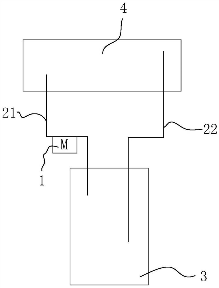
[0059] Embodiment 1 of the present application provides a control system for thermal perfusion therapy equipment. In one embodiment, specifically, as figure 2 As shown, the control system may include a variable speed peristaltic pump 1 , an infusion conduit and a heating tank 3 ; the variable speed peristaltic pump 1 may include a pump head and a driving device; the infusion conduit may include a first conduit 21 and a second conduit 22 . Wherein, one end of the first conduit 21 and one end of the second conduit 22 can be sealed in the heating tank 3, the other end of the first conduit 21 can be inserted into the human body cavity 4, and the other end of the second conduit 22 can be inserted into the human body. In the body cavity 4; or can be connected through a connecting tube derived from the body cavity, which is not limited here. The pump head can be crimped on the first conduit 21 , or the pump head can be crimped on the second conduit 22 . As those skilled in the art,...

Embodiment 2

[0075] The second aspect of the present invention provides a control method for thermal perfusion therapy equipment. The control method can be applied to the control system in Embodiment 1 above. In one embodiment, specifically, as Figure 9 As shown, control methods can include:

[0076] S10: The driving device receives a preset time-varying signal, and the preset time-varying signal includes a direction time-varying signal.

[0077] In one embodiment, the user can set a preset time-varying signal for the variable-speed peristaltic pump 1, and the drive device can receive the preset time-varying signal, so that the drive device can control the pump head to perform different directions or directions according to the preset time-varying signal. Rotation at different speeds, specifically, the preset time-varying signal may include a direction-time-varying signal, and the direction-time-varying signal may include a forward direction signal and a reverse direction signal. It can ...


PUM


Abstract

The present invention provides a control system and a control method of a device for a hyperthermic perfusion treatment. The control system comprises a variable-speed peristaltic pump, transfusion guide pipes and a heating tank body; the variable-speed peristaltic pump comprises a pump head and a driving device; the transfusion guide pipes comprises a first guide pipe and a second guide pipe; oneend of the first guide pipe and one end of the second guide pipe are arranged in the heating tank body in a sealed mode, and the pump head is connected on the first guide pipe or the second guide pipein a pressing manner; the driving device is used for receiving preset time-varying signals and controlling the pump head to rotate in a positive direction within a first preset time period accordingto the preset time-varying signals including direction time-varying signals to enable medicine liquid to enter an inner cavity of a human body from the heating tank body through the first guide pipe;and the driving device is used for controlling the pump head to rotate in an opposite direction in a second preset time period according to the preset time-varying signals to enable the medicine liquid to enter the inner cavity of the human body from the heating tank body through the second guide pipe. The control system can realize full heating of cavity walls and organs, enables the medicine liquid to flush rear sides of the organs, enables an area which is not fully heated originally under a winding-column eddy current to be fully heated, and improves a treatment effect on a patient.

Description

technical field [0001] The invention relates to the technical field of medical equipment, in particular to a control system and a control method of a heat perfusion treatment equipment. Background technique [0002] In traditional thermoperfusion therapy equipment, the liquid medicine control system usually includes pumps, infusion catheters and heating tanks. Among them, in the circulation mode, under the pressurization of the pump, the medicinal liquid can generate a certain pressure and flow rate, so that the medicinal liquid heated in the heating tank enters the inner cavity of the human body through the catheter into the body, and the pressurized Under the negative pressure generated by the pump, the medicinal liquid can flow from the human body cavity into the outlet catheter and return to the heating tank to continue heating. That is to say, under the pressure of the booster pump, the medicinal liquid can pass through the catheter into the human body cavity at a pred...

Claims


Application Information

Patent Timeline
IPC IPC(8): A61F7/12A61M31/00G05B19/05F04B43/12F04B53/08
CPCA61F7/12A61M31/00G05B19/05F04B43/12F04B53/08
Inventor 毛延发刘庭
Owner 深圳市医思美科技有限公司
Why Eureka
Try Eureka