
Clamping device suitable for machining cast valve body

A clamping device and machining technology, applied in the field of mechanical processing, can solve the problems of not meeting the processing quality requirements of cast valve bodies, workpiece offset, and inability to provide pressing force, etc., to improve machining quality and high positioning accuracy , Improve the effect of manufacturing level

Inactive Publication Date: 2021-01-01
徐州阿马凯液压技术有限公司
View PDF9 Cites 1 Cited by
  • Summary
  • Abstract
  • Description
  • Claims
  • Application Information

AI Technical Summary

Problems solved by technology

[0005] The above-mentioned fully automatic synchronous compacting machine in the prior art is only suitable for simple compacting and cannot provide accurate positioning for the workpiece. The working surface of the push plate of the adjustment mechanism is opposite and parallel to the working surface of the centralizing plate, which can only ensure that the workpiece is not skewed. Unable to provide stable and sufficient pressing force, it is easy to cause the workpiece to deviate during the milling process with changing load, which cannot meet the processing quality requirements of the cast valve body

Method used


Image

  • Clamping device suitable for machining cast valve body
  • Clamping device suitable for machining cast valve body
  • Clamping device suitable for machining cast valve body

Examples


Embodiment Construction

[0023] In order to make the object, technical solution and advantages of the present invention clearer, the present invention will be further described in detail below with reference to the accompanying drawings and embodiments. However, it should be understood that the specific embodiments described here are only used to explain the present invention, and are not intended to limit the scope of the present invention.

[0024] Unless otherwise defined, all technical terms and scientific terms used herein have the same meaning as commonly understood by those skilled in the technical field of the present invention, and the terms used in the description of the present invention herein are only to describe specific implementations The purpose of the example is not intended to limit the present invention.

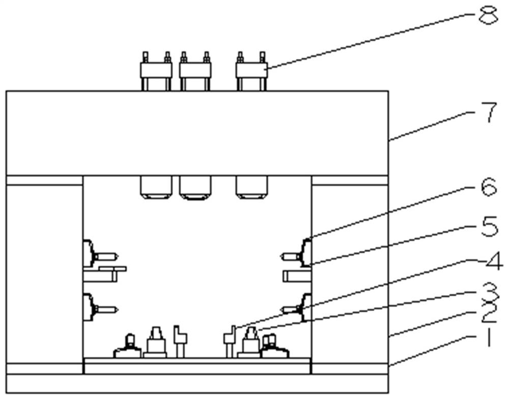
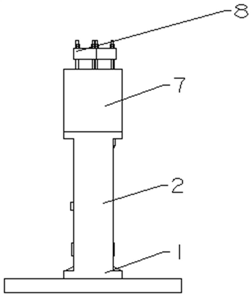
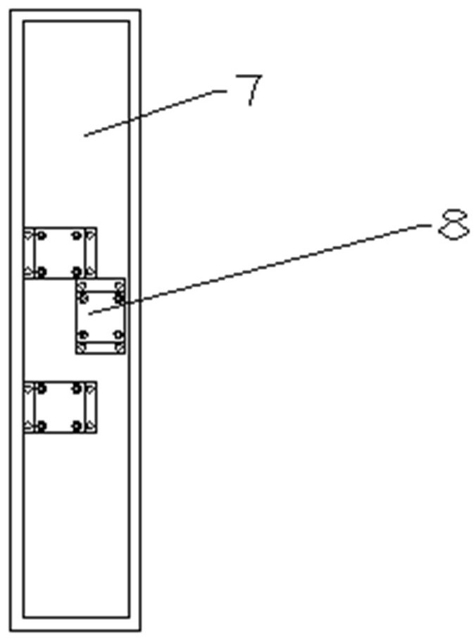
[0025] like figure 1 and figure 2 As shown, a clamping device suitable for the machining of cast valve bodies includes a clamp base 1, a clamp side plate 2, an improved positi...


PUM


Abstract

The invention discloses a clamping device suitable for casting valve body machining. The clamping device comprises a clamp base, clamp side plates, improved positioning taper pins, limiting blocks, side pressing blocks, side pressing taper pins, a clamp upper pressing plate and pressing taper pins; the improved positioning taper pins are symmetrically arranged on the clamp base, and the limiting blocks are symmetrically arranged on the clamp base through bolts; the clamp side plates are symmetrically arranged at the two ends of the clamp base; the two ends of the clamp upper pressing plate arerespectively connected with the top ends of the clamp side plates; the pressing taper pins are arranged on the clamp upper pressing plate; and the inner walls of the clamp side plates are connected with the pressing blocks and the side pressing taper pins through slender bolts. According to the clamping device, accurate positioning can be provided for a workpiece, stable and sufficient pressing force can be provided, the workpiece is not liable to deviate in the surface milling process with continuously changing load, and the machining quality requirement of a cast valve body can be met.

Description

technical field [0001] The invention relates to a clamping device suitable for machining a cast valve body, belonging to the technical field of machining. Background technique [0002] The clamping action of casting valve body machining is a particularly important step in the milling process of hydraulic multi-way valves. The quality of the clamping device directly affects the processing quality of the casting valve body. [0003] At present, there are two common clamping methods for hydraulic casting valve body machining at home and abroad. One is quick clamp clamping. Problem; the other is the clamping device using ordinary tapered positioning pins, which cannot automatically find the center, which may cause the problem of machining deviation of the valve body and affect the processing quality of the cast valve body. Therefore, the study of clamping devices suitable for machining cast valve bodies has a positive role in improving the quality of casting valve bodies and im...

Claims


Application Information

Patent Timeline
Patent Type & Authority Applications(China)
IPC IPC(8): B23Q3/06
CPCB23Q3/062
Inventor 徐明景军清荆兴亚申晓武郭靖杨宸
Owner 徐州阿马凯液压技术有限公司
Learn More