Unmanned inspection robot for power distribution room

A technology for inspection robots and power distribution rooms, applied to color TV parts, TV system parts, instruments, etc., can solve problems such as single repetitive work, achieve low safety hazards, high accuracy, and save labor time Effect

Active Publication Date: 2021-01-01
SHANGHAI DIANJI UNIV
View PDF6 Cites 5 Cited by
  • Summary
  • Abstract
  • Description
  • Claims
  • Application Information

AI Technical Summary

Problems solved by technology

This method is very simple and involves a lot of repetitive work. If the position of the power distribution cabinet is displaced later, the positioning needs to be recalibrated

Method used


Image

  • Unmanned inspection robot for power distribution room
  • Unmanned inspection robot for power distribution room
  • Unmanned inspection robot for power distribution room

Examples


Embodiment 1

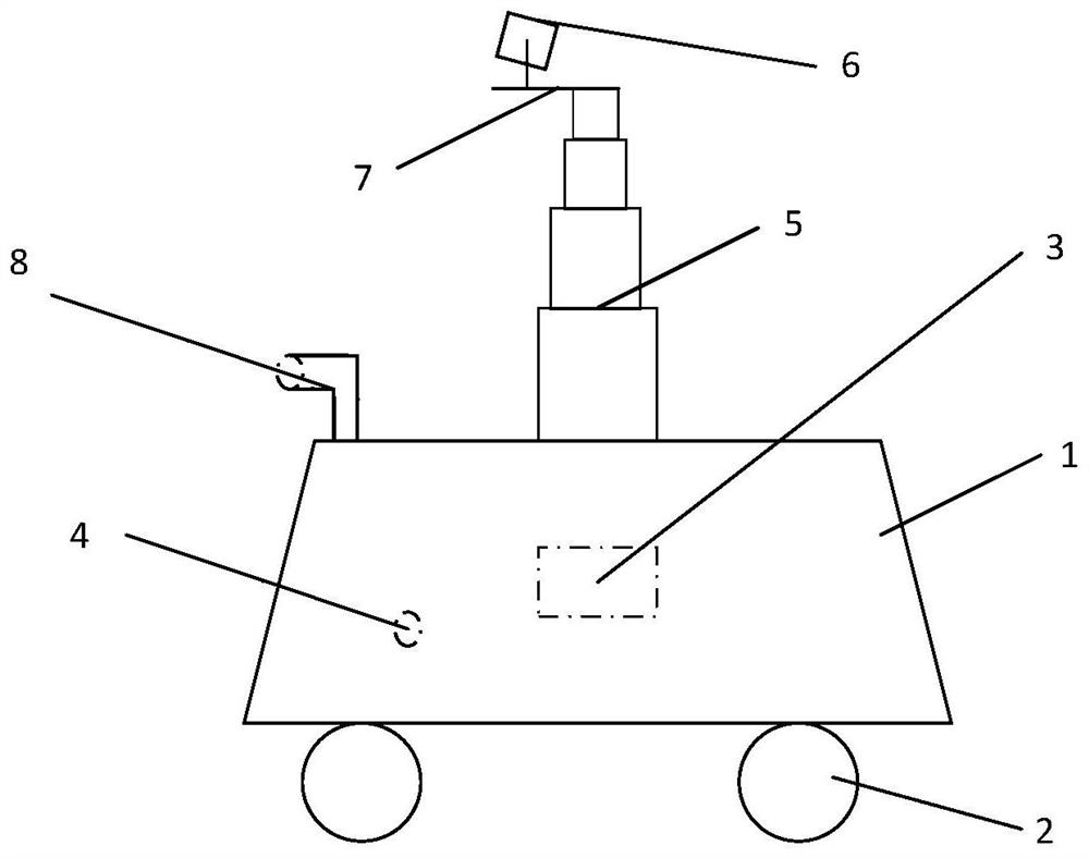
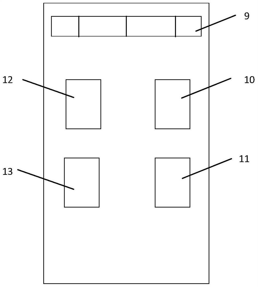
[0041] Such as figure 1 with figure 2 As shown, this embodiment provides an unmanned inspection robot for a power distribution room, including a vehicle body 1, wheels 2, a vehicle body driving mechanism and a core control panel 3. The vehicle body driving mechanism is arranged in the vehicle body 1 and is connected to the wheels 2. It is used to drive the wheel 2 to rotate, and the driving mechanism of the vehicle body is connected to the core control board 3; the unmanned inspection robot also includes a lifting platform 5 connected to the core control board 3, a camera platform 7, a camera module 6, an ultrasonic sensor 8, and a coded The DC motor of the device and the magnetic conduction sensor 9, the lifting platform 5 is connected with the camera platform 7 and the camera module 6 in turn, the lifting platform 5 is driven by a DC motor with an encoder, and the magnetic conduction sensor 9 is arranged at the bottom of the vehicle body 1;

[0042] The core control board ...

Embodiment approach

[0065] This embodiment also provides an optimal implementation mode, as follows:

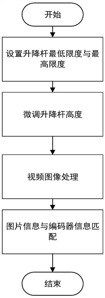
[0066] An unmanned inspection robot for power distribution room. The body structure adopts core control board 3, lifting platform 5, DC motor with encoder, high-definition camera, infrared imaging, tracking module, ultrasonic module and sound detection module. The positioning steps of the unmanned inspection robot are as follows:

[0067] S1: Set the minimum and maximum limits of the elevating head 5;

[0068] S2: The robot moves forward and takes a camera;

[0069] S3: Decompose the captured video and take out each frame of image;

[0070] S4: Perform edge detection and binarization processing on the image to obtain the block diagram where the meter is located;

[0071] S5: Screen out the correct and appropriate block diagrams and obtain location information.

[0072] The body structure, the positioning steps and the specific implementation process are described in detail below.

[0073] ...


PUM


Abstract

The invention relates to an unmanned inspection robot for a power distribution room. The unmanned inspection robot comprises a vehicle body, wheels, a vehicle body driving mechanism and a core controlboard, and further comprises a lifting holder, a camera holder, a camera module, a direct current motor with an encoder and a magnetic conduction sensor which are correspondingly connected with the core control board; and a magnetic circuit is laid in front of a power distribution cabinet in the power distribution room. The power distribution room inspection process comprises the steps of 1), controlling the lifting holder to be at the lowest height; 2), performing uniform inspection along the magnetic circuit according to the magnetic conduction sensor, and acquiring an inspection image in real time through the camera module until one round of inspection is completed; and 3), controlling the lifting holder to ascend, and repeatedly executing the steps 2) and 3). The core control board identifies an electric energy meter detecting device arranged on the power distribution cabinet from the inspection image so as to acquire the position of the power distribution cabinet and the height of the electric energy meter detecting device. According to the unmanned inspection robot for the power distribution room, compared with the prior art, manual time can be greatly saved, meanwhile, manual positioning is not needed, efficiency is greatly improved, and potential safety hazards can be reduced to the minimum.

Description

technical field [0001] The invention relates to the field of inspection robots for power distribution rooms, in particular to an unmanned inspection robot for power distribution rooms. Background technique [0002] With the rapid development of the power industry, there are more and more distribution stations and distribution rooms, and the number of inspection personnel required is also increasing day by day. However, the security is not well guaranteed. In response to this problem, more and more people have begun to study robots to replace manual inspections. Most of the robots on the market today are wheeled and rail-mounted robots. Wheeled robots are mostly aimed at substations, and indoor inspection robots use physical calibration and positioning. Guide rail machines adopt the method of adding guide rails for patrol inspection, which is also positioned through physical calibration. [0003] The working field of wheeled robot is limited, and its visual analysis is co...

Claims


Application Information

Patent Timeline
Patent Type & Authority Applications(China)
IPC IPC(8): B25J5/00B25J9/16B25J11/00G06K9/00H04N5/225
CPCB25J5/007B25J11/00B25J9/16B25J9/1694B25J9/1697B25J9/1689G06V20/10H04N23/57
Inventor 陈东张延迟赵玉琢张鑫林李鹤
Owner SHANGHAI DIANJI UNIV
Why Eureka
Try Eureka