Polyurethane elastic sponge body casting molding equipment

A polyurethane elastic, casting molding technology, applied in the direction of cleaning hollow objects, chemical instruments and methods, cleaning methods and utensils, etc., can solve the problems of residual mixed raw materials, fire danger, spontaneous combustion of foam, etc., to facilitate work, ensure sealing effect, Easy pouring effect

Inactive Publication Date: 2021-01-01
杭州乐杰新型材料科技有限公司
View PDF0 Cites 0 Cited by
  • Summary
  • Abstract
  • Description
  • Claims
  • Application Information

AI Technical Summary

Problems solved by technology

[0002]Polyurethane sponge is a low-density PU with a foam density below 18kg / m3. The method is usually that the amount of water exceeds 4.5 parts (per 100 parts of polyol), and the amount of TDI exceeds 55 parts, the heat dissipation problem of the foam is very prominent. Since the heat inside the foam is not easy to dissipate, the temperature will automatically rise above 180°C during the foaming process, which will cause the foam to spontaneously ignite and cause a fire hazard.
[0003] The polyurethane elastic sponge raw material is usually injected into the mold after mixing and stirring, but the current polyurethane elastic sponge casting process mainly has the following problems: the current casting molding equipment is difficult to adjust the gate, so it is not convenient for pouring; and It is difficult to empty the mixed raw materials inside after pouring, resulting in some mixed raw materials remaining in the reaction box, which affects the cleanliness of the reaction box

Method used


Image

  • Polyurethane elastic sponge body casting molding equipment
  • Polyurethane elastic sponge body casting molding equipment
  • Polyurethane elastic sponge body casting molding equipment

Examples


Embodiment Construction

[0020] Embodiments of the present invention will be described below with reference to the drawings. In the process, in order to ensure the clarity and convenience of illustration, we may exaggerate the width of the lines or the size of the constituent elements in the diagram.

[0021] In addition, the following terms are defined based on the functions in the present invention, and may be different according to the user's or operator's intention or practice. Therefore, these terms are defined based on the entire content of this specification.

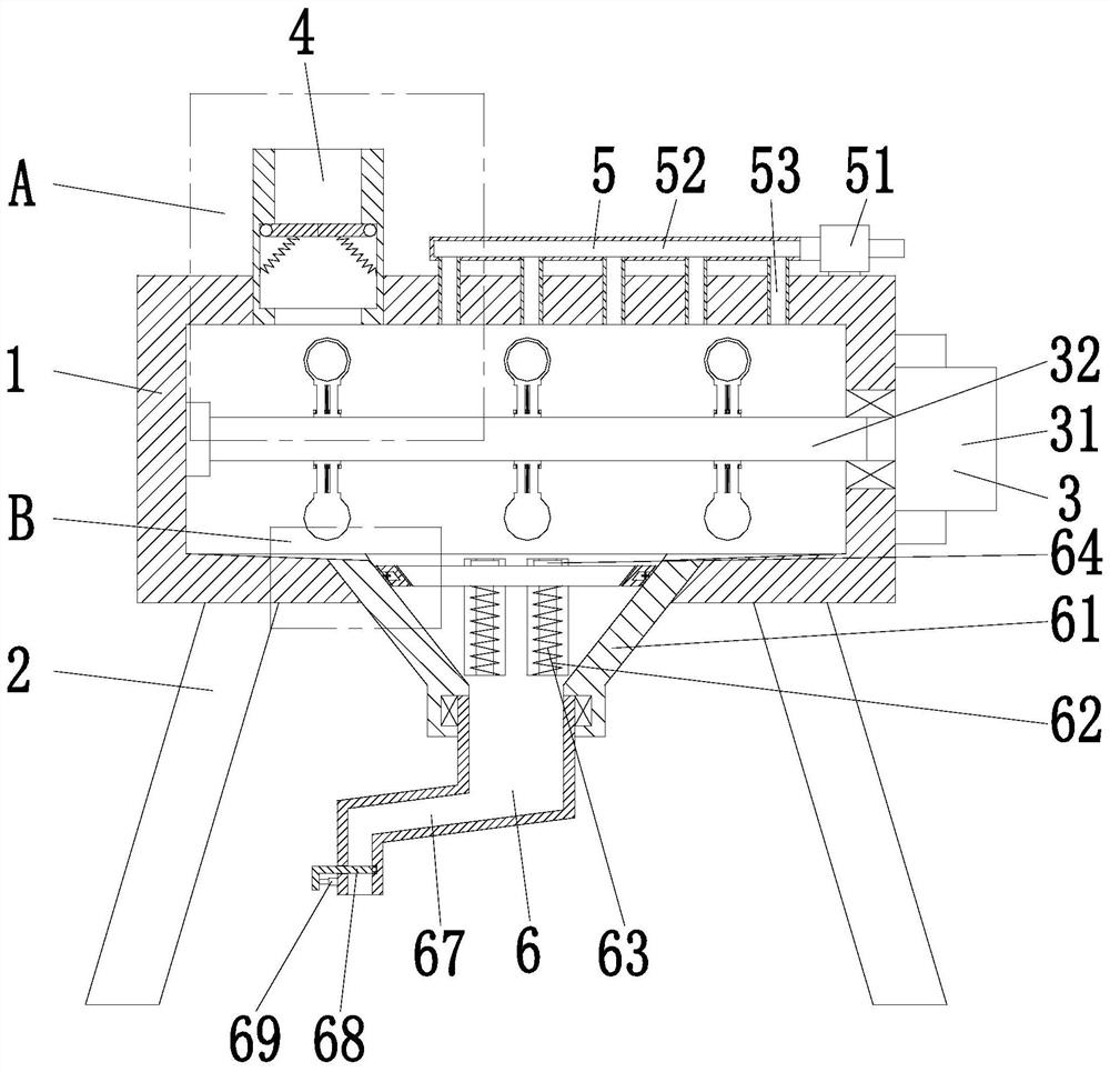
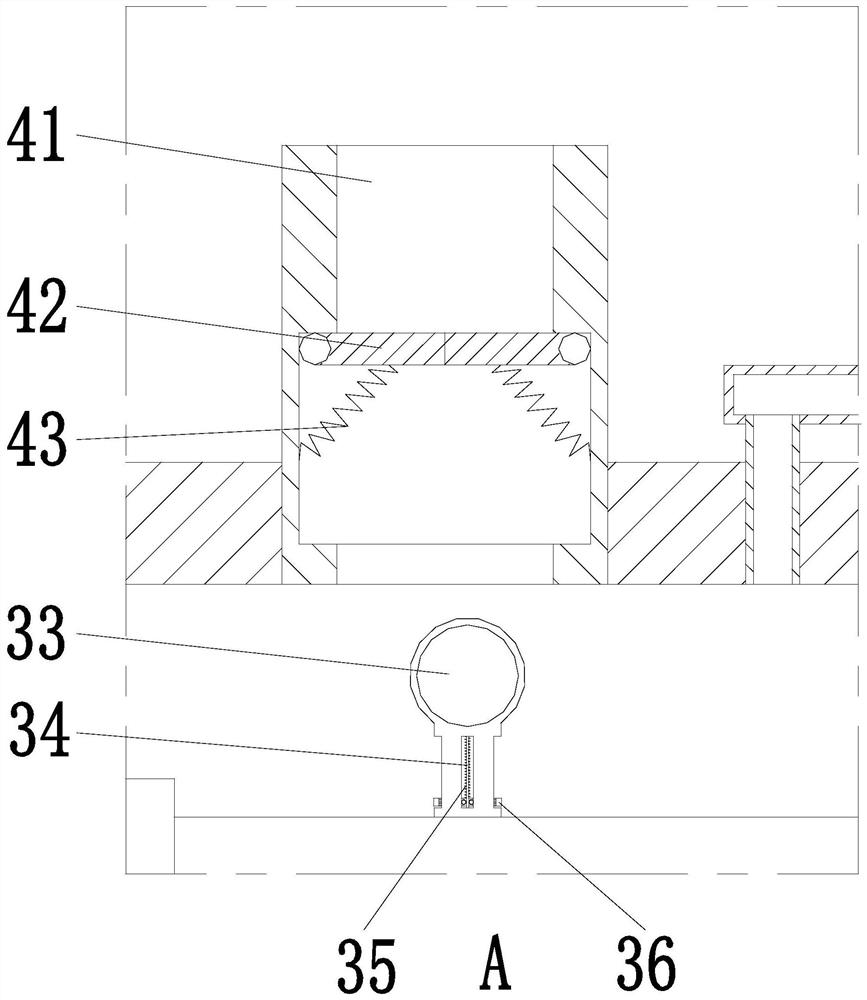
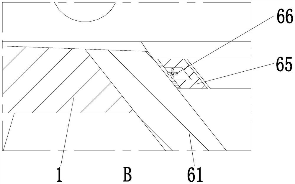
[0022] Such as Figure 1 to Figure 3 As shown, a polyurethane elastic sponge casting molding equipment includes a reaction box 1, a foot 2, a stirring device 3, a feeding unit 4, an air control unit 5 and a discharge device 6; the lower end of the reaction box 1 is evenly provided with The legs 2 are located inside the reaction box 1, and the stirring device 3 is installed in a horizontal manner through the bearing. The upper left oute...


PUM

PropertyMeasurementUnit
densityaaaaaaaaaa

Abstract

The invention provides polyurethane elastic sponge body casting molding equipment which comprises a reaction box, supporting legs, a stirring device, a feeding unit, a pneumatic control unit and a discharging device, wherein the supporting legs are uniformly arranged at the lower end of the reaction box; the stirring device is transversely arranged in the reaction box through a bearing; the feeding unit is arranged on the outer wall of the left side of the upper end of the reaction box and communicates with the interior of the reaction box;the pneumatic control unit is arranged on the outer wall of the right side of the upper end of the reaction box and communicates with the interior of the reaction box; and the discharging device is arranged in the middle of the lower end of the reactionbox. The problem that in the existing polyurethane elastic sponge body casting molding process,casting molding equipment is difficult to adjust a casting opening, and consequently casting is carried out inconveniently is solved; and the problem that after pouring, mixed raw materials in the reaction box are difficult to empty, so that part of the mixed raw materials remain in the reaction box, andthe cleanness in the reaction box is influenced is solved.

Description

technical field [0001] The invention relates to the technical field of casting equipment, in particular to a polyurethane elastic sponge casting molding equipment. Background technique [0002] Polyurethane sponge is a low-density PU with a foam density below 18kg / m3. The method is usually that the amount of water exceeds 4.5 parts (per 100 parts of polyol), and the amount of TDI exceeds 55 parts. The heat dissipation problem of the foam is very prominent. The heat is not easy to dissipate. During the foaming process, the temperature will automatically rise to more than 180°C, which will cause the foam to ignite spontaneously, resulting in a fire hazard. [0003] The polyurethane elastic sponge raw material is usually injected into the mold after mixing and stirring, but the current polyurethane elastic sponge casting process mainly has the following problems: the current casting molding equipment is difficult to adjust the gate, so it is not convenient for pouring; and It ...

Claims


Application Information

Patent Timeline
Patent Type & Authority Applications(China)
IPC IPC(8): B29C39/24B29C39/22B29B7/16B29B7/24B29B7/84B29B7/26B08B9/087
CPCB08B9/087B29B7/16B29B7/24B29B7/26B29B7/84B29C39/22B29C39/24
Inventor 刘梦茹朱彬祥
Owner 杭州乐杰新型材料科技有限公司
Why Eureka
Try Eureka