Automatic conveying device for clamp piece machining

A technology of automatic conveying device and pliers, which is applied in the direction of conveyor control device, conveyor objects, transportation and packaging, etc., can solve the problems of high labor cost for pliers processing, low processing efficiency of pliers, and increased safety hazards, etc. Achieve the effects of improving the processing efficiency of the pliers, reducing labor intensity and labor costs, and improving stability

Inactive Publication Date: 2021-01-01
湖南精专自动化技术有限公司
View PDF0 Cites 2 Cited by
  • Summary
  • Abstract
  • Description
  • Claims
  • Application Information

AI Technical Summary

Problems solved by technology

[0004] The object of the present invention is to provide an automatic conveying device for pliers processing in order to solve the above problems, which solves the problem that the current pliers need to go through multiple steps of blanking, feeding, clamping and discharging during the processing of the current pliers. Therefore, in the process of conveying the pliers, multiple stations are required for manual operation, resulting in high labor costs for pliers processing, and at the same time, there are increased safety hazards, resulting in low processing efficiency, high labor intensity, and low practicability. poor disadvantage

Method used


Image

  • Automatic conveying device for clamp piece machining
  • Automatic conveying device for clamp piece machining
  • Automatic conveying device for clamp piece machining

Examples


Embodiment Construction

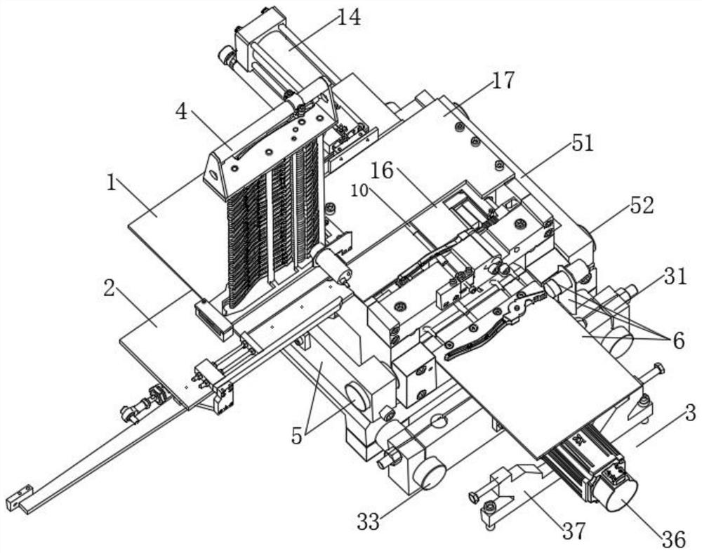
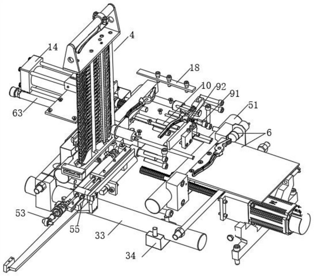
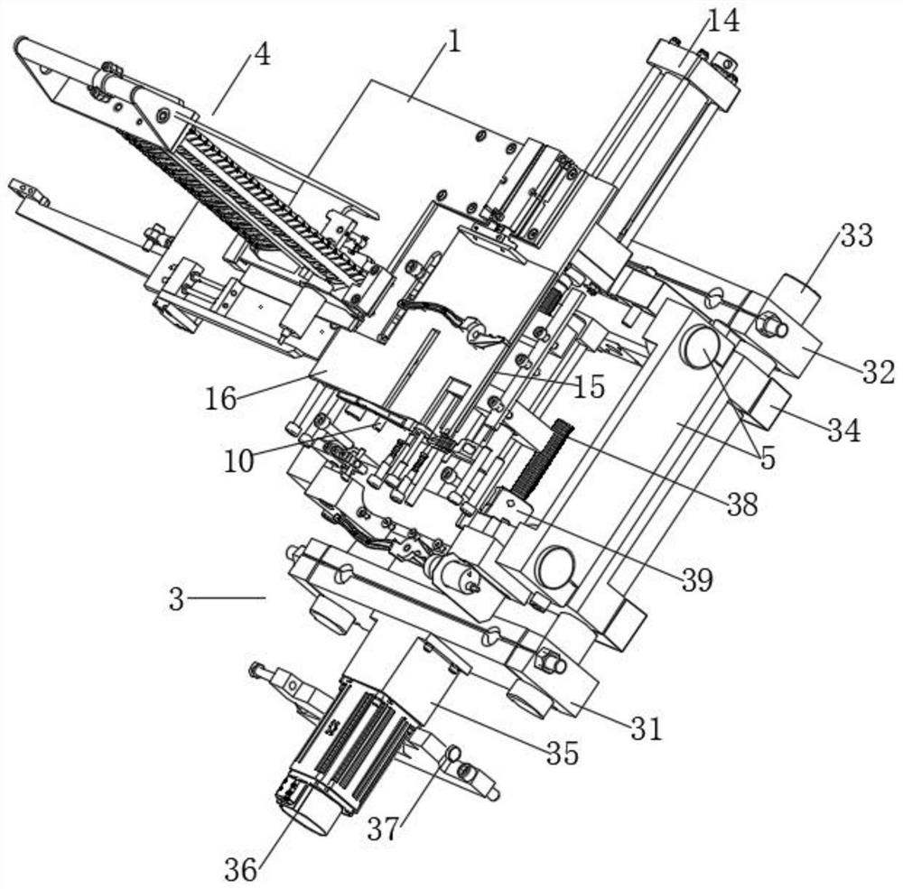
[0024] Such as Figure 1-6As shown, this specific embodiment adopts the following technical solutions: an automatic conveying device for pliers processing, including a manual discharge device 1, a primary moving seat 3, a material collecting device 4, a secondary moving seat 5 and a discharge mechanism 6 , one side of the manual discharge device 1 is equipped with a feeding base plate 2, a first-level mobile seat 3 is provided below the manual discharge device 1, and a collection device 4 is provided on the top of the manual discharge device 1, so The top of the first-level mobile seat 3 is provided with a secondary mobile seat 5, and the side of the secondary mobile seat 5 away from the material collecting device 4 is provided with a discharge mechanism 6, and the top of the secondary mobile seat 5 is close to the discharge mechanism. One side of the 6 is fixedly installed with an integrated fixed clamp block 7, and the side of the integrated fixed clamp block 7 close to the ...


PUM


Abstract

The invention discloses an automatic conveying device for clamp piece machining. The automatic conveying device for clamp piece machining comprises a manual discharging device, a first-stage moving seat, a material collecting device, a second-stage moving seat and a discharging mechanism, wherein a feeding bottom plate is installed on one side of the manual discharging device; the first-stage moving seat is arranged below the manual discharging device; the material collecting device is arranged at the top of the manual discharging device; the second-stage moving seat is arranged at the top ofthe first-stage moving seat; a discharging mechanism is arranged on the side, away from the material collecting device, of the second-stage moving seat; an integrated fixed clamping block is fixedly installed on the side, close to the discharging mechanism, of the top of the second-stage moving seat; and a first workpiece position leaning piece and a second workpiece position leaning piece are fixedly installed on the side, close to the discharging mechanism, of the integrated fixed clamping block; The automatic conveying device for clamp piece machining has the beneficial effects that automatic discharging, feeding, clamping machining and discharging, and clamp piece machining automatic conveying operation in the clamp piece machining process are achieved, the clamp piece machining efficiency is improved, the labor cost is reduced, the conveying safety is higher, an induction assembly is used for discharging and discharging induction, and the clamp piece conveying stability is improved.

Description

Technical field: [0001] The invention belongs to the technical field of pliers conveying, in particular to an automatic conveying device for pliers processing. Background technique: [0002] With the continuous improvement of the economic level and the continuous progress of science and technology, the processing equipment is gradually improved. Pliers are a kind of hand tool used to clamp and fix the workpiece or twist, bend and cut the wire. The shape of the pliers is V-shaped, and usually includes three parts: the handle, the pliers jaw and the pliers mouth. The pliers are generally made of carbon structural steel. heat treatment; [0003] At present, during the processing of the pliers, the pliers need to be transported through multiple steps of blanking, feeding, clamping and discharging. Therefore, in the process of pliers transportation, multiple stations are required for manual operation, resulting in High labor costs and increased potential safety hazards lead to ...

Claims


Application Information

Patent Timeline
Patent Type & Authority Applications(China)
IPC IPC(8): B65G47/82B65G43/08B65G47/88B65G47/74
CPCB65G43/08B65G47/74B65G47/82B65G47/883
Inventor 王再德
Owner 湖南精专自动化技术有限公司
Why Eureka
Try Eureka