Lint removing device for textile fabric printing and dyeing

A technology for textile fabrics and printing, which is applied to the field of hair removal devices for printing and dyeing textile fabrics, can solve problems such as troublesome fixing, reduced practicability, and inconvenience to use.

Active Publication Date: 2021-01-01
绍兴市德帏纺织科技有限公司
View PDF3 Cites 1 Cited by
  • Summary
  • Abstract
  • Description
  • Claims
  • Application Information

AI Technical Summary

Problems solved by technology

[0004] The object of the present invention is to provide a hair removal device for printing and dyeing of textile fabrics, to solve the problem that the existing hair removal device for printing and dyeing of textile cloths proposed in the background art is fixed by bolts and straight plates when the textile cloth is fixed in use, which is troublesome. Inconvenient to use, reducing the problem of practicality

Method used


Image

  • Lint removing device for textile fabric printing and dyeing
  • Lint removing device for textile fabric printing and dyeing
  • Lint removing device for textile fabric printing and dyeing

Examples


Embodiment 1

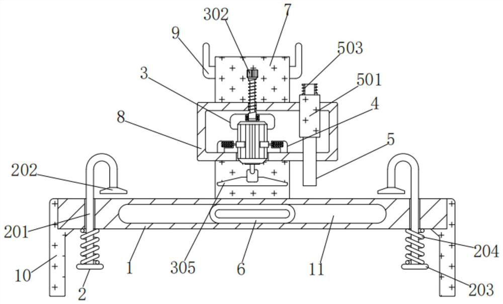
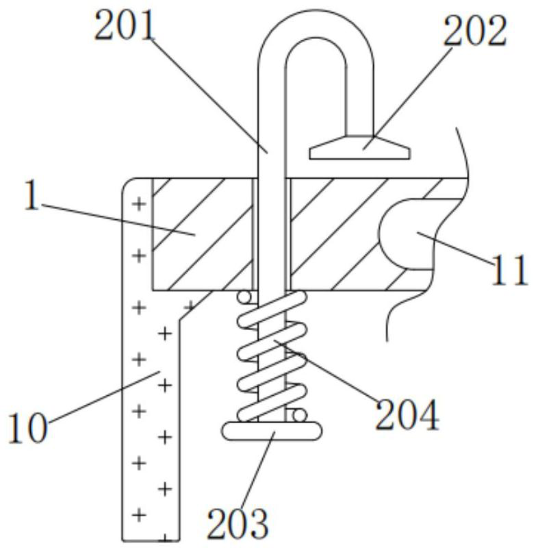
[0038] A hair removal device for printing and dyeing of textile fabrics, comprising a base plate 1, a fixing mechanism 2 is installed on the left and right sides of the front of the base plate 1, and the fixing mechanism 2 includes a curved rod 201, a curved block 202, a short plate 203 and a first spring 204, The outer wall of the curved rod 201 is matched with the front left side of the bottom plate 1. The curved rod 201 moves up and down through the front left side of the bottom plate 1 under force. It is fixedly connected with the top of the short plate 203, and the lower part of the outer wall of the curved rod 201 is socketed with the inner wall of the first spring 204. Fixed connection, the curved rod 201, the short plate 203, the first spring 204 and the bottom plate 1 form a telescopic mechanism, and the curved rod 201 rebounds through the first spring 204 after being moved under force;

[0039] The front of the bottom plate 1 is processed with a chute 11, the inner w...

Embodiment 2

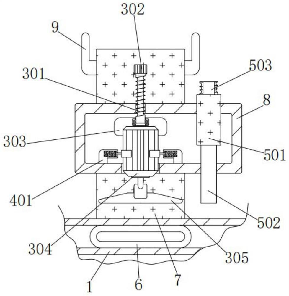
[0041] As an option, see figure 1 , 3 And 4, textile fabric printing and dyeing hair removal device, the inwall of square frame 8 is equipped with power mechanism 3, and power mechanism 3 comprises threaded rod 301, handle 302, support 303, motor 304 and cutter 305, and the outer wall of threaded rod 301 and The top threaded connection of square frame 8, the top of threaded rod 301 is fixedly connected with the bottom of handle 302, and handle 302 is convenient to rotate threaded rod 301, and the bottom of threaded rod 301 is connected with the top of support 303 rotation, and the bottom of threaded rod 301 The force is rotated through the bearing on the top of the support 303. The inner wall of the support 303 is fixedly connected to the top of the outer wall of the motor 304. The model of the motor 304 is Y2-1. The lower part of the outer wall of the motor 304 is matched with the bottom of the square frame 8. Power moves up and down through the bottom of the square frame 8,...

Embodiment 3

[0044] As an option, see figure 1 , 4 And 5, the hair removal device for printing and dyeing of textile fabrics, the left and right sides of the inner wall bottom of the square frame 8 are equipped with a protection mechanism 4, and the protection mechanism 4 includes a curved plate 401, a second spring 402, a protruding rod 403 and a circular arc plate 404 , the bottom of the bent plate 401 is affixed to the bottom left side of the inner wall of the square frame 8, the left side of the inner wall above the front of the bent plate 401 is affixed to the left side of the second spring 402, and the right side of the second spring 402 is affixed to the protruding rod The left side of 403 is fixedly connected, and the protruding rod 403 rebounds through the second spring 402 after being moved under force. The outer wall of the protruding rod 403 cooperates with the gap on the right side of the inner wall above the front of the curved plate 401, and the protruding rod 403 passes thr...


PUM


Abstract

The invention discloses a lint removing device for textile fabric printing and dyeing. The device comprises a bottom plate, fixed mechanisms are installed on the left side and the right side of the front face of the bottom plate correspondingly, the fixed mechanisms comprise bent rods, bent blocks, short plates and first springs, the outer wall of each bent rod is in clearance fit with the left side of the front face of the bottom plate, and the upper portions of the outer walls of the bent rods are fixedly connected with the tops of the bent blocks. The bent rods are elastically supported bythe first springs of the fixed mechanisms, the bent rods cooperate with the bent blocks to fix a textile part, fixing is convenient, using is convenient, practicability is improved, the position of acutter is adjusted, the position of the cutter is prevented from sliding down, operation is facilitated, and normal work is guaranteed; and protruding rods are supported by second springs of protection mechanisms to cooperate with arc plates to clamp a motor, motor shaking force is reduced, motor collision is avoided, damage is prevented, and the service life is prolonged; and an adsorption mechanism cooperates with the rotating cutter, lint removal and adsorption are achieved at the same time, the machining difficulty is reduced, the trouble of later-period cleaning is omitted, and popularization is convenient.

Description

technical field [0001] The invention relates to the technical field of hair removal devices for printing and dyeing of textile cloth, in particular to a hair removal device for printing and dyeing of textile cloth. Background technique [0002] Textile fabrics are divided into weft-knitted fabrics and warp-knitted fabrics according to the weaving method. Weft-knitted fabrics are often made of low-elastic polyester yarns or special-shaped polyester yarns, nylon yarns, cotton yarns, and wool yarns. [0003] The existing hair removal device for printing and dyeing of textile cloth uses bolts to fix the textile cloth with a straight plate when in use, which is troublesome to fix, inconvenient to use, and reduces the practicability, and the position of the cutter is fixed, and the position is easy to slide for a long time and cannot be adjusted. It affects the normal work of the textile fabric, and the shaking of the motor is easy to collide with the square frame, causing damage ...

Claims


Application Information

Patent Timeline
Patent Type & Authority Applications(China)
IPC IPC(8): D06C13/00D06G1/00
CPCD06C13/00D06G1/00
Inventor 周长根
Owner 绍兴市德帏纺织科技有限公司
Why Eureka
Try Eureka