Air deflector structure and air conditioner using same

A technology for air deflectors and air conditioners, which is applied in air conditioning systems, applications, and household heating, etc. It can solve the problems of reducing resistance, large air resistance of air conditioners, and loud noise, so as to increase air volume, reduce noise and power consumption, and ensure airtightness Effect

Pending Publication Date: 2021-01-01
GREE ELECTRIC APPLIANCES INC
View PDF0 Cites 0 Cited by
  • Summary
  • Abstract
  • Description
  • Claims
  • Application Information

AI Technical Summary

Problems solved by technology

[0002] The air deflector is an important part of the air conditioner, mainly used to control the direction of the air flow. Generally, the air conditioner has one or two air deflectors, namely the first air deflector and the second air deflector; see below Figure 4 , the first air deflector is generally located below the air outlet of the air conditioner, the second air deflector is above the air outlet, and the length of the second air deflector is much shorter than that of the first air deflector, and it mainly rotates inside the air conditioner outlet to serve as an auxiliary guide Due to the effect of air flow, the existing air deflector will bring greater resistance to the air duct. The length difference between the second air deflector and the first air deflector is large, and the second air deflector rotates inside the air conditioner. The wind panel cannot form an effective air duct to reduce resistance, resulting in large air resistance, low air volume, high noise, high power consumption, and inability of the hot air flow to fall, etc., which can no longer meet the requirements of energy saving and comfort

Method used


Image

  • Air deflector structure and air conditioner using same
  • Air deflector structure and air conditioner using same
  • Air deflector structure and air conditioner using same

Examples


Embodiment 1

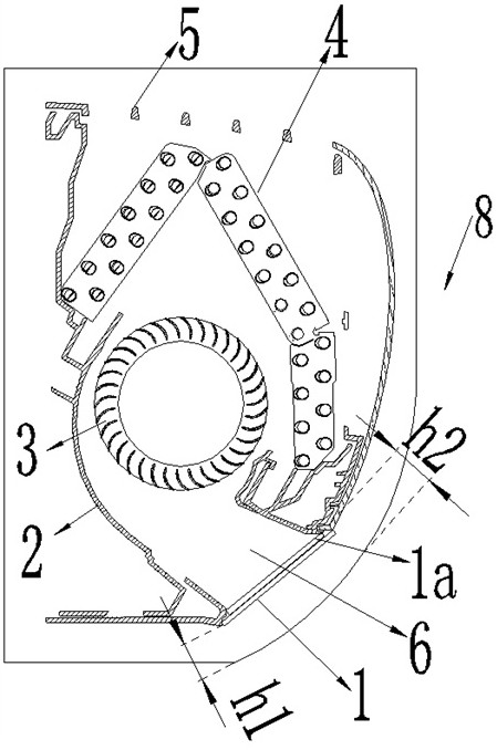
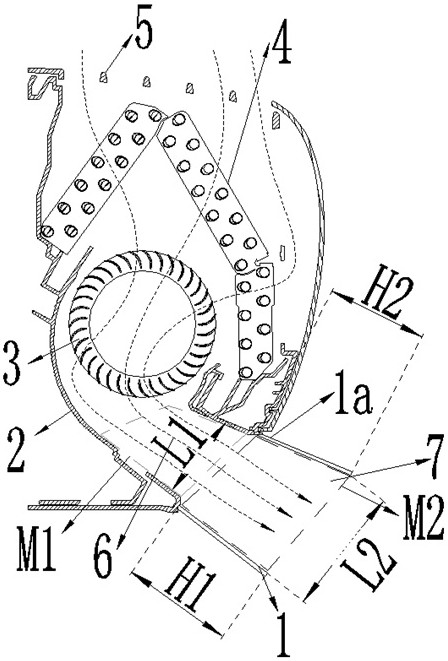
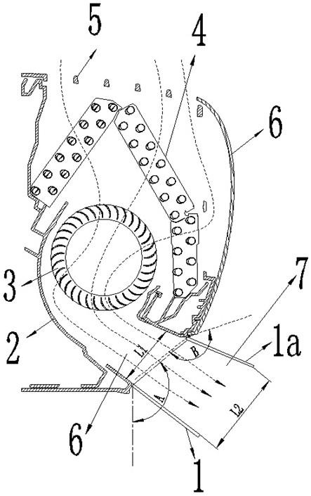
[0027] see Figure 1-3 , a wind deflector structure, including a second wind deflector 1a and a first wind deflector 1, the first wind deflector 1 and the second wind deflector 1a are overlapped and intersected at the first end of the bottom shell 2 The air outlet 6, the rotation center point of the second air guide plate 1a is set on the upper side of the first air outlet 6, the rotation center point of the first air guide plate 1 is set on the lower side of the first air outlet 6, The first air deflector 1 and the second air deflector 1a are rotated to the outside of the first air outlet 6 to form the second air outlet 7, and the length H2 of the second air deflector 1a is greater than or equal to the second air deflector The distance h2 from the center of rotation of 1a to the exterior 8 of the air conditioner, the plate length H1 of the first air deflector 1 is greater than or equal to the distance h1 from the center of rotation of the first air deflector 1 to the exterior...

Embodiment 2

[0038] An air conditioner is applied with the above-mentioned wind deflector structure.


PUM


Abstract

The invention particularly discloses an air deflector structure and an air conditioner using the same. The air deflector structure comprises a second air deflector and a first air deflector, the firstair deflector and the second air deflector are arranged at a first air outlet in the tail end of a bottom shell in an overlapping and intersecting mode, the rotating center point of the second air deflector is arranged on the upper side of the first air outlet, the rotating center point of the first air deflector is arranged on the lower side of the first air outlet, the first air deflector and the second air deflector rotate towards the outer side of the first air outlet to be opened to form a second air outlet, the plate length H2 of the second air deflector is larger than or equal to the distance h2 from the rotating center point of the second air deflector to the exterior of the air conditioner, and the plate length H1 of the first air deflector is larger than or equal to the distanceh1 from the rotating center point of the first air deflector to the exterior of the air conditioner. The second air deflector forms an effective extending air duct of the first air outlet and plays arole in diffusion and resistance reduction, so that the air volume of the air conditioner is increased, noise and power consumption are reduced, hot air flow can be effectively pressed downwards, andthe carpet type heating effect is achieved.

Description

technical field [0001] The invention relates to the field of wind deflectors and air conditioners, in particular to a structure of wind deflectors and an air conditioner using the same. Background technique [0002] The air deflector is an important part of the air conditioner, mainly used to control the direction of the air flow. Generally, the air conditioner has one or two air deflectors, namely the first air deflector and the second air deflector; see below Figure 4 , the first air deflector is generally located below the air outlet of the air conditioner, the second air deflector is above the air outlet, and the length of the second air deflector is much shorter than that of the first air deflector, and it mainly rotates inside the air conditioner outlet to serve as an auxiliary guide Due to the effect of air flow, the existing air deflector will bring greater resistance to the air duct. The length difference between the second air deflector and the first air deflector ...

Claims


Application Information

Patent Timeline
Patent Type & Authority Applications(China)
IPC IPC(8): F24F13/10F24F13/24F24F1/0014
CPCF24F1/0014F24F13/10F24F13/24
Inventor 曹雷邹建煌耿付帅陈付齐和浩浩
Owner GREE ELECTRIC APPLIANCES INC
Why Eureka
Try Eureka