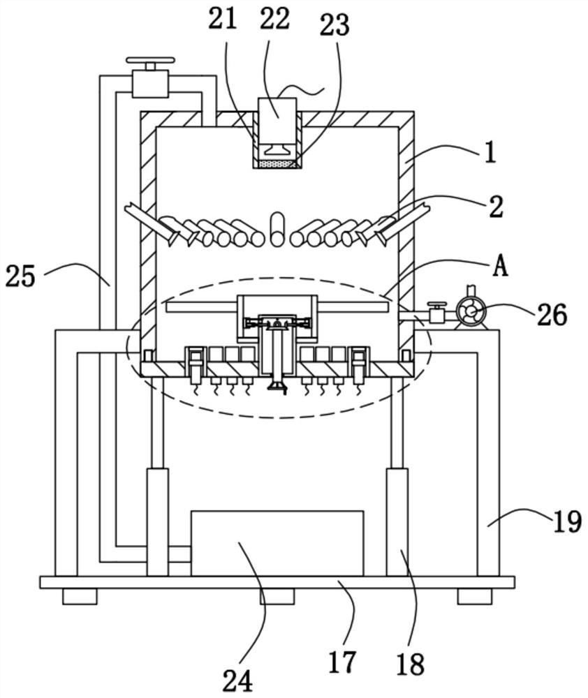
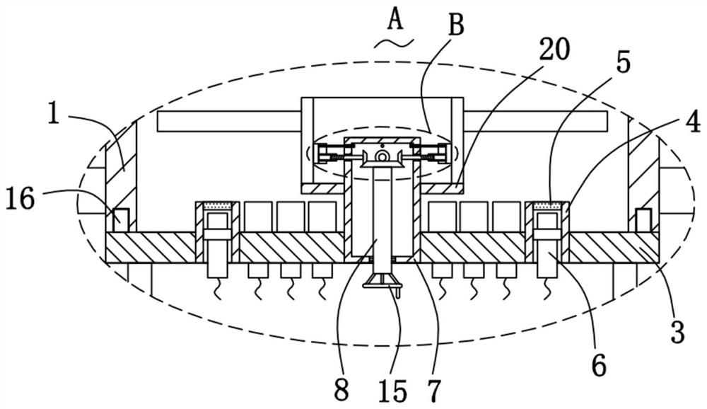
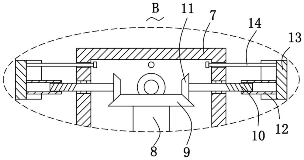
Aero-engine blade thermal barrier coating thermal fatigue testing device based on temperature sensor

A temperature sensor, aero-engine technology, applied in measuring devices, instruments, scientific instruments, etc., can solve the problems of single judgment method and inaccurate judgment, and achieve the effect of simple, convenient and fast installation, avoiding separation, and conducive to burning.

Pending Publication Date: 2021-01-01
江苏航运职业技术学院
View PDF0 Cites 0 Cited by
  • Summary
  • Abstract
  • Description
  • Claims
  • Application Information

AI Technical Summary

Problems solved by technology

[0002] Some patients will be in a coma state after the operation. At this time, the patient cannot breathe spontaneously. Generally, a ventilator is used to assist the breathing. Whether the patient is awake or not, they will notify the medical staff, so that the medical staff can know the patient's awakening status, pull out the trachea, and let the patient breathe spontaneously. This kind of identification of the patient's awakening situation depends entirely on the judgment of the personnel, and the judgment method is single. When the patient When there are no nurses or family members around, the waking state depends only on the ward rounds of the medical staff, and there are certain limitations in the observation of the medical staff only by eyes, which makes the judgment not accurate enough

Method used


Image

  • Aero-engine blade thermal barrier coating thermal fatigue testing device based on temperature sensor
  • Aero-engine blade thermal barrier coating thermal fatigue testing device based on temperature sensor
  • Aero-engine blade thermal barrier coating thermal fatigue testing device based on temperature sensor

Examples


Embodiment Construction

[0031] In order to make the technical problems, technical solutions and beneficial effects to be solved by the present invention clearer, the present invention will be further described in detail below in conjunction with the accompanying drawings and embodiments. It should be understood that the specific embodiments described here are only used to explain the present invention, not to limit the present invention.

[0032] It should be noted that when an element is referred to as being “fixed”, “installed”, “connected” or “disposed” with another element, it may be directly on the other element or indirectly on the other element. It is to be understood that the terms "upper", "lower", "front", "rear", "left", "right", "vertical", "horizontal", "top", "bottom", "inner" The orientation or positional relationship indicated by , "outside", etc. is based on the orientation or positional relationship shown in the drawings, and is only for the convenience of describing the present inv...


PUM


Abstract

The invention discloses an aero-engine blade thermal barrier coating thermal fatigue testing device based on a temperature sensor. The device comprises a box body having the bottom with an opening, aplurality of flame spraying guns installed in the box body, having the tail ends extending out of the box body, and distributed in an annular array mode, a lifting plate arranged at the bottom of thebox body and matched with the opening, and multiple fixing pipes penetrating through the lifting plate, fixedly connected with the lifting plate, and distributed in an annular array mode. By arrangingthe box body, a test is completely carried out in a closed container, a plurality of flame spraying guns are arranged to realize firing of the blade, temperature measurement is carried out through aplurality of temperature sensors, and then computer analysis is carried out, so that the thermal barrier coating on the blade can be subjected to thermal insulation capability detection.

Description

technical field [0001] The invention relates to the technical field of medical equipment, in particular to a thermal fatigue testing device for thermal barrier coatings of aeroengine blades based on a temperature sensor. Background technique [0002] Some patients will be in a coma state after the operation. At this time, the patient cannot breathe spontaneously. Generally, a ventilator is used to assist the breathing. Whether the patient is awake or not, they will notify the medical staff, so that the medical staff can know the patient's awakening status, pull out the trachea, and let the patient breathe spontaneously. This kind of identification of the patient's awakening situation depends entirely on the judgment of the personnel, and the judgment method is single. When the patient When there are no nurses or family members around, the waking state depends only on the ward rounds of the medical staff, and the medical staff have certain limitations in observing with their ...

Claims


Application Information

Patent Timeline
IPC IPC(8): G01N3/60G01N3/06G01N3/04
CPCG01N3/04G01N3/068G01N3/60G01N2203/0073G01N2203/04G01N2203/0641
Inventor 姚达曹将栋黄健陈燕姜伯晨
Owner 江苏航运职业技术学院
Why Eureka
Try Eureka