Rivet feeding device and method

A feeding device and rivet technology, which is applied in the field of self-piercing riveting equipment, can solve problems such as not being able to meet the rivet feeding, and achieve the effect of avoiding automatic falling off, avoiding movement and angle deviation

Active Publication Date: 2021-01-05
SHANDONG UNIV
View PDF8 Cites 1 Cited by
  • Summary
  • Abstract
  • Description
  • Claims
  • Application Information

AI Technical Summary

Problems solved by technology

[0003] The rivet feeder equipped with the traditional self-piercing riveting gun generally uses compressed air to send a rivet to the initial feeding position through a plastic tube to prevent the rivet from turning over and tilting. The rivet feeder mostly works in a horizontal state; Azimuth rivet feeding

Method used


Image

  • Rivet feeding device and method
  • Rivet feeding device and method

Examples


Embodiment 1

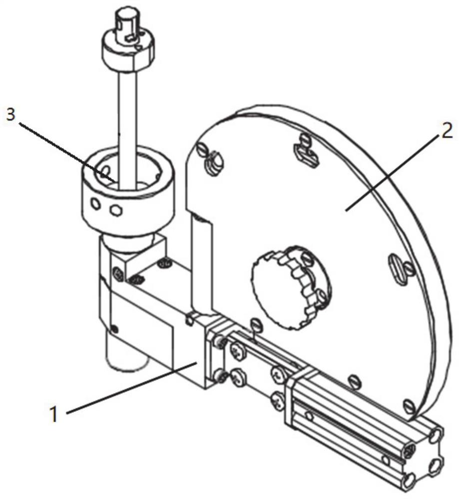
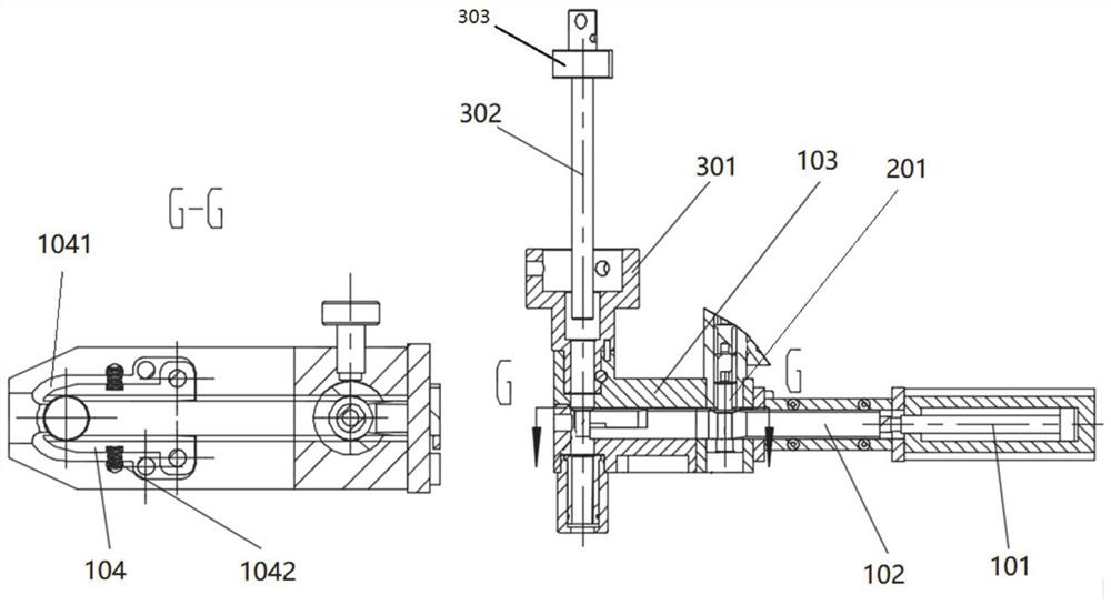
[0039] A rivet feeding device, comprising: a rivet gun 1, a hopper 2 and a feeding unit 3; the rivet gun 1 includes a T-shaped body 103 and a cylinder 101 connected thereto; the T-shaped body 103 is provided with a corresponding T type material channel; the push rod 102 of the cylinder 101 is socketed in the material channel at the end of the T-shaped body 103 vertical bar away from the horizontal bar; the material bin 2 is arranged in an arch shape, and the material bin 2 is fixed on On the vertical rod of the rivet gun 1; one end of the arched silo is provided with a silo port 201, and the silo port 201 communicates with the material channel; the feeding unit 3 includes a connecting sleeve 301 provided with a through hole A cylindrical punch 302 is arranged in the through hole of the connecting sleeve 301 ; the feeding unit 3 is socketed on one end of the horizontal rod of the T-shaped body 103 through the connecting sleeve 301 .

[0040] The cross-section of the push rod 10...

Embodiment 2

[0050] Embodiment 2 of the present invention discloses a rivet feeding method, which adopts the rivet feeding device described in Embodiment 1, and specifically includes the following steps:

[0051] Load a certain number of rivets into the silo 2 so that the rivets are closely arranged linearly in the silo;

[0052] Install the silo 2 on the rivet gun to realize the communication between the silo port 201 and the material channel;

[0053] The push rod 102 of the cylinder pushes the rivet from the initial position to the working position. In the working position, under the action of the spring 1042, the chuck 104 can hold the rivet and wait for the punch to move down for riveting;

[0054] Further, the push rod 102 can only push one rivet in one displacement, and after the push rod 102 is retracted, the rear rivets move down sequentially, waiting for the next cycle;

[0055] The rivets in the material storage channel in the material storage bin of the present invention are a...


PUM


Abstract

The invention relates to a rivet feeding device and method. The rivet feeding device comprises a rivet gun, a material bin and a feeding unit. The rivet gun comprises a T-shaped body and an air cylinder connected with the T-shaped body. A corresponding T-shaped material channel is arranged in the T-shaped body. A push rod of the air cylinder is sleeved with the material channel at the end, away from a horizontal rod, of a vertical rod of the T-shaped body. The material bin is arranged to be in an arch shape, and the material bin is fixed to the vertical rod of the rivet gun. A material bin opening is formed in one end of the arch-shaped material bin and is communicated with the material channel. The feeding unit comprises a connecting sleeve provided with a through hole, wherein a cylindrical punch is arranged in the through hole of the connecting sleeve. The feeding unit sleeves one end of the horizontal rod of the T-shaped body through the connecting sleeve. By means of the rivet feeding device and method, rivets in a storage channel in the material bin are closely and linearly arranged, and the rivets are not affected by gravity and work in multiple directions under the action of a pushing device. A chuck is arranged at the joint of a horizontal material channel body and a vertical material channel body in the T-shaped material channel, so that the rivets are prevented fromautomatically falling off under the action of gravity.

Description

technical field [0001] The invention relates to the field of self-piercing riveting equipment, in particular to a rivet feeding device and method. Background technique [0002] Self-piercing riveting is a zero-link technology used to connect two or more metal sheets or non-metal sheets. It uses a special rivet to penetrate the sheet and expands the hollow structure at the tail of the rivet under the action of the riveting die at the bottom of the sheet. Forms a strong riveted joint without piercing the underlying sheet. Self-piercing riveting gun is a kind of self-piercing riveting equipment that can automatically complete rivet replenishment. It is widely used in the fields of new energy vehicle aluminum body production, light steel structure production, bridge wire slot production and sign production. [0003] The rivet feeder equipped with the traditional self-piercing riveting gun generally uses compressed air to send a rivet to the initial feeding position through a pl...

Claims


Application Information

Patent Timeline
Patent Type & Authority Applications(China)
IPC IPC(8): B21J15/32
CPCB21J15/32
Inventor 田新诚方纬华崔龙丁录国宋锐马昕周乐来李贻斌
Owner SHANDONG UNIV
Why Eureka
Try Eureka