
Traceless direction treatment mechanism

A technology of direction and trace, applied in the direction of conveyors, conveyor objects, rotary conveyors, etc., can solve the problems of inability to automatically complete the roller guide and supply function, inconvenient equipment debugging, and low process precision, so as to save Repeated matching time, easy replacement, well-designed effect

Pending Publication Date: 2021-01-05
龚培生
View PDF0 Cites 0 Cited by
  • Summary
  • Abstract
  • Description
  • Claims
  • Application Information

AI Technical Summary

Problems solved by technology

[0007] Aiming at the deficiencies of the prior art, the present invention provides a non-trace guiding mechanism, which solves the problems that the traditional equipment cannot automatically complete the guiding and supplying functions of the rollers, the process precision is low, and the equipment debugging is inconvenient.

Method used


Image

  • Traceless direction treatment mechanism
  • Traceless direction treatment mechanism
  • Traceless direction treatment mechanism

Examples


Embodiment Construction

[0023] The following will clearly and completely describe the technical solutions in the embodiments of the present invention with reference to the accompanying drawings in the embodiments of the present invention. Obviously, the described embodiments are only some, not all, embodiments of the present invention. Based on the embodiments of the present invention, all other embodiments obtained by persons of ordinary skill in the art without making creative efforts belong to the protection scope of the present invention.

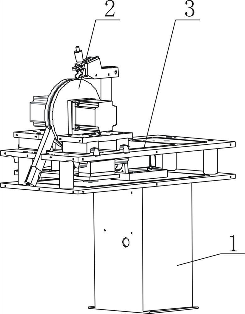
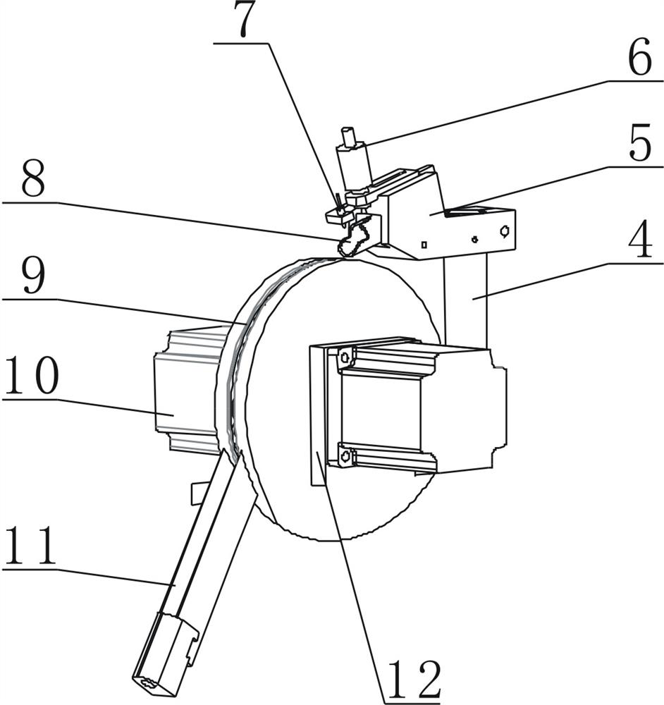
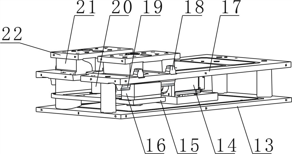
[0024] like Figure 1-3 As shown, the present invention provides a technical solution: a traceless orientation mechanism, including a support square tube 1, a roller guide assembly 2 and an automatic adjustment assembly 3, the automatic adjustment assembly 3 is installed on the upper end of the support square pipe 1, and the rolling The sub-guiding assembly 2 protrudes from the inside of the automatic adjustment assembly 3, and the roller guiding assembly 2 is...


PUM


Abstract

The invention discloses a traceless direction treatment mechanism. The traceless direction treatment mechanism comprises a supporting square pipe, a roller guide assembly and an automatic debugging assembly. The automatic debugging assembly is installed at the upper end of the supporting square pipe, the roller guide assembly is arranged in the automatic debugging assembly in a protruding manner,and the roller guide assembly is used for guide treatment of rollers. Rollers vibrated out by a vibration mechanism are orderly arranged into a straight line to enter the roller guide assembly, the roller guide assembly orderly conducts direction treatment processing on the rollers and sends the rollers to the next procedure for assembly work, and the automatic debugging assembly can complete exchange between different models of the rollers. The roller guide assembly internally comprises a stand column, a rotary disc and a V-shaped discharging port. By arranging the supporting square pipe, theroller guide assembly and the automatic debugging assembly, the problems that traditional equipment cannot automatically complete the guide and supply effects of rollers, the process precision is low, and equipment debugging is inconvenient are solved.

Description

technical field [0001] The invention relates to the technical field of production of tapered rollers, in particular to a no-mark orientation mechanism. Background technique [0002] Tapered roller bearings are separable bearings, and the inner and outer rings of the bearing have tapered raceways. This type of bearing is divided into different structural types such as single row, double row and four row tapered roller bearings according to the number of rows of rollers installed. Single row tapered roller bearings can bear radial loads and axial loads in one direction. When the bearing bears radial load, an axial component force will be generated, so another bearing that can bear the axial force in the opposite direction is needed to balance it. Widely used in automobiles, rolling mills, mining, metallurgy, plastic machinery and other industries. [0003] Tapered rollers need to use a straightening mechanism for the sorting and supply of rollers during production and proce...

Claims


Application Information

Patent Timeline
IPC IPC(8): B65G43/08B65G29/02B65G47/24
CPCB65G29/02B65G43/08B65G47/24B65G2203/044B65G2207/08
Inventor 龚培生
Owner 龚培生
Learn More