Eureka AIR delivers breakthrough ideas for toughest innovation challenges, trusted by R&D personnel around the world.

Conveying device for food detection

A conveying device and food detection technology, which is applied in the direction of conveyors, conveyor objects, transportation and packaging, etc., can solve the problems of limited feeding speed, easy to pile up, and inconvenient feeding, so as to reduce labor intensity and improve Detection efficiency, effect of avoiding confusion

Active Publication Date: 2021-01-05
广东可味巧克力食品有限公司
View PDF6 Cites 4 Cited by
  • Summary
  • Abstract
  • Description
  • Claims
  • Application Information

AI Technical Summary

Problems solved by technology

The structure of the invention is simple to improve, and the bagged food can be detected while being transported, and the unqualified ones are blocked by the baffle plate, and at the same time, there is a side cylinder to push it to the operating table, and an alarm is also provided to alarm, and the whole operation is automated , and the detection effect is good in turn; but when the device detects the bagged food, the bagged food in transportation is easy to pile up, which makes this feeding method unsuitable and lacks practicability
[0004] After retrieval, the invention patent with the publication number CN110745470A discloses a bagged food delivery detection device, which relates to the field of food detection technology; Manual blanking, when working in multiple directions, the speed of the staff’s blanking is limited, which affects the progress of the entire food delivery inspection; specifically includes the bottom plate, and the four corners of the top outer wall of the bottom plate are equipped with fixed plates

Method used


Image

  • Conveying device for food detection
  • Conveying device for food detection
  • Conveying device for food detection

Examples


Embodiment 1

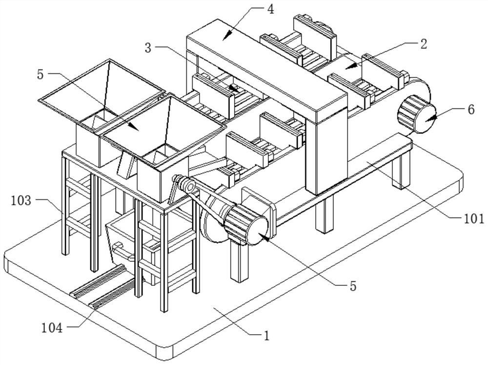
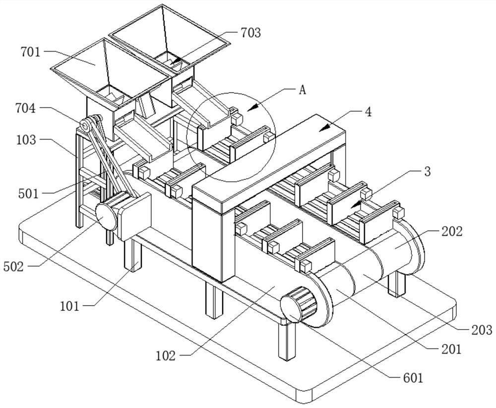
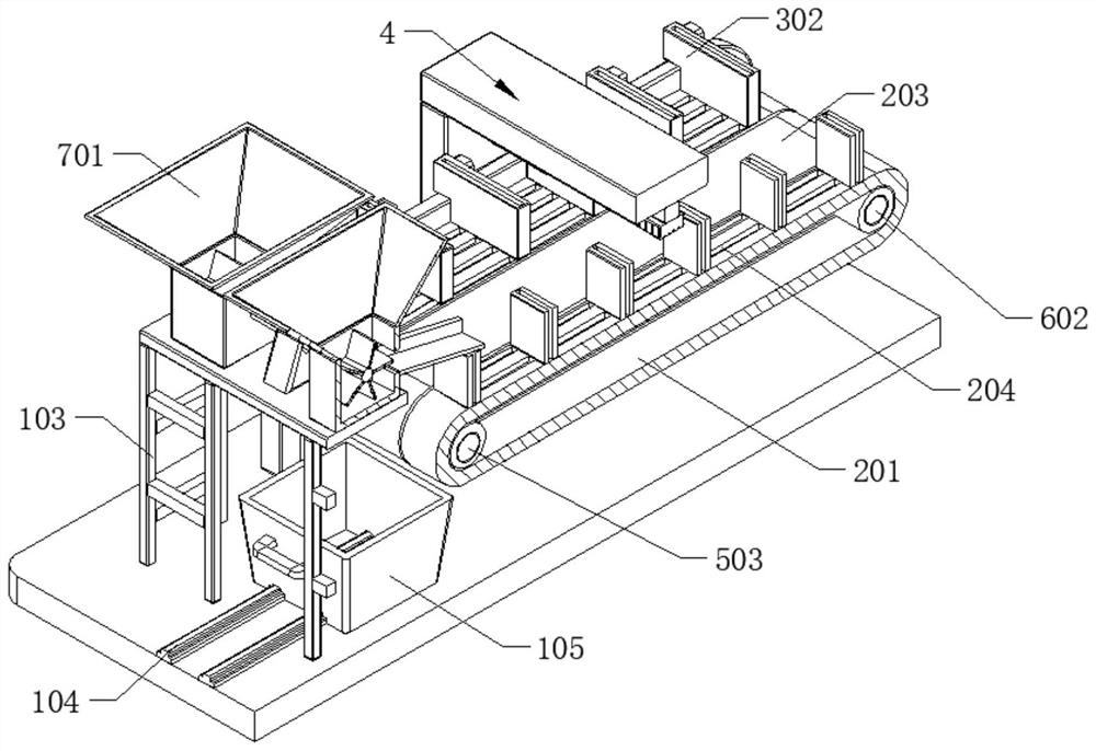
[0035] refer to Figure 1-6 , a conveying device for food detection, comprising a bottom plate 1 and a conveying mechanism 2, a first support frame 101 is connected to the top wall of the bottom plate 1, a protective plate 102 is connected to the top wall of the first support frame 101, and the conveying mechanism 2 is connected to the protective On the inner wall of the plate 102, on the top wall of the first support frame 101, a detection assembly 4 is also connected, and the detection assembly 4 is matched with the conveying mechanism 2. The conveying mechanism 2 includes a first conveyor belt 201, a second conveyor belt 202 and a third conveyor belt 203. A conveyor belt 201 and the second conveyor belt 202 have the same conveying direction and are staggered with each other. The second conveyor belt 202 is opposite to the conveying direction of the first conveyor belt 201. The first conveyor belt 201 and the second conveyor belt 202 are connected with a conveying assembly 3 ...

Embodiment 2

[0040] refer to Figure 1-8 , a conveying device for food detection, which is basically the same as in Embodiment 1, and further, a conveying device for food detection, comprising a base plate 1 and a conveying mechanism 2, the top wall of the base plate 1 is connected with a first support frame 101, The top wall of the first support frame 101 is connected with a protective plate 102, the conveying mechanism 2 is connected on the inner wall of the protective plate 102, and the detection assembly 4 is also connected on the top wall of the first support frame 101, and the detection assembly 4 matches the conveying mechanism 2, The conveying mechanism 2 comprises a first conveyor belt 201, a second conveyor belt 202 and a third conveyor belt 203. The first conveyor belt 201 and the second conveyor belt 202 have the same conveying direction and are interlaced with each other. The second conveyor belt 202 is opposite to the first conveyor belt 201 conveying direction. The first con...

Embodiment 3

[0048] refer to Figure 1-5 , a conveying device for food detection, which is basically the same as that of Embodiment 1, furthermore, the feeding assembly 7 includes a feeding funnel 701 and a discharging tray 702, and the feeding funnel 701 is connected to the top wall of the second support frame 103, One end of the discharge tray 702 is connected to the outer wall of the feeding funnel 701 , and the other end is matched with the conveying mechanism 2 .

[0049] The inside of the feeding funnel 701 is also provided with a shifting assembly 703, the shifting assembly 703 includes a third rotating shaft 704 and a shifting plate 705, the third rotating shaft 704 is connected to the inner wall of the feeding funnel 701, and one end of the third rotating shaft 704 Through the feed funnel 701 and connected to the output end of the first drive motor 502 through the first belt 501, the material shifting plate 705 is connected on the outer wall of the third rotating shaft 704, and is...


PUM


Abstract

The invention discloses a conveying device for food detection and belongs to the technical field of food detection devices. The conveying device for food detection comprises a bottom plate and a conveying mechanism. The conveying mechanism is connected to a top wall of the bottom plate and comprises a first conveyor belt, a second conveyor belt and a third conveyor belt, conveying assemblies are connected to the top walls of the first and second conveyor belts, a first driving assembly and a second driving assembly are separately arranged on the outer wall of a protecting plate, an output endof the first driving assembly is matched with the first conveyor belt and the second conveyor belt, separately, the second driving assembly is matched with the third conveyor belt, a feeding assemblyis connected to the top wall of the bottom plate through a second supporting rack, the feeding assembly is connected to the first driving assembly through a first belt, and the output end of the feeding assembly is matched with the conveying mechanism. The conveying device for food detection can avoid a condition that it is inconvenient to unload materials as food is accumulated in a detection process effectively and further can reduce the labor intensity and improve the work efficiency effectively.

Description

technical field [0001] The invention relates to the technical field of food testing devices, in particular to a food testing delivery device. Background technique [0002] Food is usually composed of carbohydrates, fats, proteins or water, which can provide nutrition or pleasure for humans or organisms by eating or drinking; with the improvement of people's living standards and health awareness, how to improve food quality and reduce food Residues of harmful substances, ensuring the quality and safety of food is an important task in the current food production and processing industry. [0003] After retrieval, the invention with the publication number CN201820807059.5 discloses a bagged food delivery detection device, including a conveyor belt, a portal frame covering the conveyor belt, a metal detector installed on the portal frame, and a portal frame There is an upper cylinder at the rear, the piston rod of the upper cylinder is vertically downward and a baffle is install...

Claims


Application Information

Patent Timeline
Patent Type & Authority Applications(China)
IPC IPC(8): B65G47/04B65G15/30B65G47/52B07C5/36B07C5/38
CPCB65G47/04B65G15/30B65G47/52B07C5/36B07C5/38
Inventor 闫春会
Owner 广东可味巧克力食品有限公司
Why Eureka
Eureka Blog
Learn More