Feeding conveying system of automatic shrimp peeling machine
A technology of conveying system and feeding conveyor belt, which is applied in the direction of conveyors, conveyor objects, conveyor control devices, etc., and can solve the problems of low shrimp peeling efficiency, low efficiency, and low automation of manual feeding.
Inactive Publication Date: 2021-01-05
佛山松瀚智能设备有限公司
11 Cites 0 Cited by
AI-Extracted Technical Summary
Problems solved by technology
[0008] In order to overcome the defects and deficiencies in the above-mentioned prior art, the application provides a feeding and conveying system for an automatic shrimp peeling machine. Arrangement of feeding materials leads to prob...
Method used
As another preferred embodiment of the application, with reference to accompanying drawing 8 of specification sheet, present embodiment provides a kind of technical scheme of the feeding conveying method of automatic shrimp peeling machine, and the invention purpose of this technical scheme is to solve existing stripping The feeding and conveying method of the shrimp machine has the problems of poor automation, low efficiency of feeding arrangement, food safety and low efficiency of peeling shrimp. The technical proposal adopts a manipulator for feeding, which can effectively realize the automatic feeding and arrangement of raw shrimps, and can effectively improve the efficiency of feeding and arranging raw shrimps and the shrimp peeling efficiency of the shrimp peeling machine.
As another preferred embodiment of the present application, the present embodiment provides a kind of technical implementation scheme of the feeding system of automatic shrimp peeling machine, and this technical scheme also can solve above-mentioned peeling shrimp machine in the prior art and adopts manual mode The feeding arrangement of raw shrimp leads to the problems of low degree of automation and low efficiency of peeling shrimp. This application is on the basis of the original shrimp peeling machine equipment, making minor improvements to the feeding tray, and adding manipulator feeding, so as to improve the efficiency of shrimp peeling, improve the efficiency of feeding and arranging raw shrimp, and improve the efficiency of peeling shrimp. The degree of automation of the machine. The technical plan is as follows:
Common manipulators on the market are equipped with visual acquisition devices, but generally the visual acquisition devices are integrated at the execution end of the manipulator, and this technical solution specifically makes the visual acquisition device 4 and the manipulator action execution device 5 independent of each other Installation is due to the feed conveying system of the present technical proposal, which requires higher positioning and grasping ability of the manipulator 3, and the manipulator 3 must accurately grasp the specific position on the raw shrimp 10, otherwise the accurate positioning of the shrimp cannot be completed. Positioning and placement, this technical solution separates the visual acquisition device 4 from the manipulator action execution device 5, just to ensure the accuracy of visual acquisition. Since the execution end 5 of the manipulator will vibrate to a certain extent, if the visual acquisition device 4 is installed at the execution end, there will be more interference in the collected image information, which is not conducive to the accurate positioning of the execution end of the manipulator. In the technical solution, the vision acquisition device and the manipulator action execution device are separately set, which can effectively ensure the accuracy of image acquisition and the stability of the manipulator's positioning and grasping.
Common manipulators on the market are equipped with visual acquisition devices, but generally the visual acquisition devices are integrated at the execution end of the manipulator, and this technical solution specifically separates the visual acquisition device 4 and the manipulator action execution device 5 Installation is due to the feed conveying system of the present technical proposal, which requires higher positioning and grasping ability of the manipulator 3, and the manipulator 3 must accurately grasp the specific position on the raw shrimp 10, otherwise the accurate positioning of the shrimp cannot be completed. Positioning and placement, this technical solution separates the visual acquisition device 4 from the manipulator action execution device 5, just to ensure the accuracy of visual acquisition. Since the execution end 5 of the manipulator will vibrate to a certain extent, if the visual acquisition device 4 is installed at the execution end, there will be more interference in the collected image information, which is not conducive to the accurate positioning of the execution end of the manipulator. In the technical solution, the vision acquisition device and the manipulator action execution device are separately set, which can effectively ensure the accuracy of image acquisition and the stability of the manipulator's positioning and grasping.
Further preferred technical scheme, the execution end of described manipulator is provided with sucker 14, in this technical scheme, can adopt the mode of absorbing to carry out the grasping of raw material shrimp, implements comparatively simple, with reference to accompanying drawing 5 of specification sheet, includes There are two suction cups 14, one of which is the positioning suction cup as the positioning reference point for the manipulator to grab the shrimp. The suction cup corresponds to the grasping reference point 23 on the raw shrimp according to the placement state of the raw shrimp, so as to complete the raw shrimp 10 positions for grabbing and placing.
Further preferred technical s...
Abstract
The invention discloses a feeding conveying system of an automatic shrimp peeling machine, and relates to the technical field of shrimp processing machinery. The feeding conveying system involves a feeding conveying belt, a mechanical arm and a feeding disc, wherein a movement track of a shrimp containing groove forms an annular face, the annular face is parallel to the horizontal plane, a feedingport is located in one side of the annular-face-shaped feeding disc, and a discharging port is located in the other side of the annular-face-shaped feeding disc; and the feeding conveying belt is installed on the feeding port side of the feeding disc, and the mechanical arm is installed above the feeding conveying belt and the feeding disc. According to the system, by arranging the mechanical armand redesigning a structure of the feeding disc, the shrimp peeling efficiency can be improved, the feeding and arranging efficiency of raw shrimps is improved, and the automation degree of the shrimp peeling machine is improved.
Application Domain
ConveyorsControl devices for conveyors +1
Technology Topic
EngineeringFishery +3
Image
Examples
- Experimental program(4)
Example Embodiment
[0084] Example 1
[0085] As a preferred embodiment of the present application, this embodiment discloses a feeding and conveying system for an automatic shrimp peeling machine. Shrimp feeding, the efficiency of shrimp feeding is slow, the degree of automation of the shrimp peeling machine is low, and the efficiency of peeling shrimp is low.
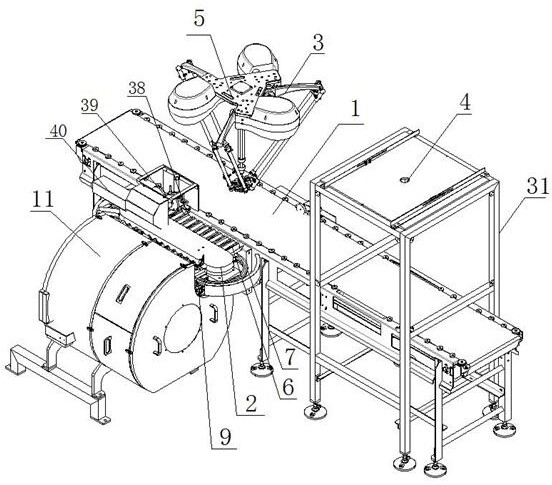
[0086] Depend on Figure 1-4 Shown, a kind of feeding conveying system of automatic shrimp peeling machine comprises feeding tray 2, and described feeding tray 2 is provided with some shrimp grooves 6, and described feeding tray is provided with feed inlet 8 and outlet. The feed port 9, the feed conveying system of this embodiment also includes a feed conveyor belt 1 and a manipulator 3. Refer to the attached figure 1 and 2 , compared with the prior art, the present embodiment changes the vertical structure of the feeding tray 2 in the existing shrimp peeling machine body into a horizontal structure, that is, an annular surface 7 formed by the movement track of the shrimp trough 6 , the annular surface 7 is parallel to the horizontal plane; as figure 2As shown, the feeding port 8 is located on one side of the annular surface feeding tray 2, and the discharging port 9 is located on the other side of the annular surface feeding tray 2; the feeding conveyor belt 1 is installed On the side of the feeding port 8 of the feeding tray 2, and the length direction of the shrimp trough 6 located at the feeding port 8 is perpendicular to the conveying direction of the feeding conveyor belt; 10. The manipulator 3, which is grabbed and placed in the shrimp trough 6, is installed above the feeding conveyor belt 1 and the feeding tray 2.
[0087] In this embodiment, the technical solution changes the structure of the feeding tray 2, and changes the original vertical structure into a horizontal structure. Figure 11 and figure 2 It can be clearly seen that the structure of the feeding tray in the technical solution is obviously different from that of the feeding tray in the main body of the existing shrimp peeling machine. The effect is embodied in: without changing the length of the horizontal conveying section 13 of the feeding tray 2 in the main body 11 of the existing shrimp peeling machine, the horizontal feeding tray of this technical solution can increase the arrangement of the horizontal feeding tray in the case of the same length. Arrange the quantity of raw shrimp.
[0088] And if the body of the shrimp peeling machine in the prior art wants to add a set of feeding conveyor belt 1 and manipulator 3, without changing the structure of the feeding tray 2, the feeding conveyor belt 1 and manipulator 3 can only be set in the On the other side of the feeding tray 2 relative to the shell 12 of the shrimp peeling machine, refer to the appendix of the instruction manual. Image 6 ,Right now Image 6 The position shown in , this setting method is easily thought of by those skilled in the art, but this setting method, compared with the setting method of this technical solution, has defects, that is, this kind of arrangement will cause the movement of the manipulator 3 The longer the stroke, the lower the frequency of grasping by the manipulator, the conveying speed of the matching feeding tray 2 will also decrease, and the rotation speed of the active turntable component 29 matching the feeding tray 2 will also decrease, resulting in reduced shrimp peeling efficiency. . Specifically in:
[0089] Refer to the manual attached Image 6 , under the condition that the length of the feeding tray 2 of this technical solution and the shrimp trough 6 of the feeding tray 2 of the main body 11 of the shrimp peeling machine of the prior art are the same, the structure of the feeding tray 2 of this technical solution can shorten the length of the manipulator 3 movement itinerary.
[0090] At present, the main body of the shrimp peeling machine has restrictions on the position where the raw shrimp can be placed in the shrimp tank. It is necessary to expose a part of the shrimp tail, that is, the shrimp tail is facing the side of the discharge port. The horizontal feeding tray provided in this technical solution 2. When feeding shrimp, it is not necessary to turn the tail of the shrimp towards the side of the outlet, but to the side of the inlet, that is, towards the side of the feeding conveyor belt 1. In the case of ensuring the shrimp feeding requirements, the length of the shrimp trough is the same, and the position of the raw shrimp on the feeding conveyor belt is the same, please refer to the appendix of the instruction manual. Image 6 , the structure of the feeding tray 2 of the shrimp peeling machine body 11 of the prior art requires the manipulator 3 to move the shrimp tail 28 toward the side of the discharge port 9, and the distance it moves is L2, and the distance that the manipulator 3 moves in this technical solution is L1, by Image 6 As shown, L2 is obviously larger than L1, that is to say, in the same scenario, the vertical feeding tray 2 of the prior art will increase the moving stroke of the manipulator. However, this technical solution will shorten the moving stroke of the manipulator, so that the stroke of the manipulator 3 when placing the shrimp is shorter, the frequency of picking and releasing is faster, and the running speed of the feeding tray can be increased, so that the speed of the matching shrimp peeler can also be adjusted according to The speed of the feeding pan is correspondingly increased, making the shrimp peeling more efficient.
[0091] In this embodiment, the feeding tray 2 further includes a feeding tray mounting frame 32 and a feeding driving member 34 , and the feeding tray mounting frame 32 is provided with a feeding material that matches the running track of the shrimp trough 6 . Track 33, the feeding servo motor is installed on the feeding tray mounting frame, and the feeding tray mounting frame is provided with a driving sprocket and a driven sprocket, and the feeding driving part is sleeved on the driving sprocket and the driven sprocket On the sprocket, the shrimp trough is arranged horizontally, one end close to the feeding driving part is connected with the feeding driving part, and the middle part of the shrimp trough is connected with the feeding track. Driven by the feeding driving part and limited by the feeding track, The shrimp trough is set to rotate along the feeding track; the driving sprocket, the driven sprocket and the feeding driving part are covered on the feeding tray mounting frame through the feeding protective cover. Both ends of the feeding tray are also provided with arc-shaped guard plates.
[0092] The feeding tray is also provided with a shrimp management device, the shrimp management device includes a shrimp management drive motor, a shrimp management mounting frame, a shrimp management eccentric disc and a shrimp management piece, and the shrimp management servo motor is installed on the shrimp management installation frame, And it is located above the movement track of the feeding port and the discharging port of the feeding tray; the shrimp management piece is installed on the eccentric disc, and the shrimp management servo motor drives the shrimp management eccentric disc to rotate, thereby driving the shrimp management piece to move up and down, and the conveying Arrange to the raw shrimp below it.
[0093] Further preferred technical solutions, with reference to the description attached figure 1 , the manipulator 3 includes a visual collection device 4 and a manipulator action execution device 5, the visual collection device 4 is relatively independent from the manipulator action execution device 5, and the manipulator action execution device 5 is installed on the feeding tray 2 and the feeding conveyor belt. 1 , the visual acquisition device 4 is installed above the feeding conveyor belt 1 through the visual acquisition mounting bracket 31 , and is located in front of the manipulator action execution device 5 along the conveying direction of the feeding conveyor belt 1 .
[0094] The common manipulators on the market are equipped with visual acquisition devices, but generally the visual acquisition device is integrated in the execution end of the manipulator, and this technical solution specifically installs the visual acquisition device 4 and the manipulator action execution device 5 independently of each other. As for the feeding conveying system of this technical solution, the positioning and grasping ability of the manipulator 3 is required to be high, and the manipulator 3 must accurately grasp the specific position on the raw shrimp 10, otherwise the accurate positioning and placement of the shrimp cannot be completed. , this technical solution separates the visual acquisition device 4 and the manipulator action execution device 5 to ensure the accuracy of visual acquisition. Since the manipulator action execution end 5 will shake to a certain extent, if the visual acquisition device 4 is set at the execution end, there will be more interference in the collected image information, which is not conducive to the accurate positioning of the manipulator execution end. In the technical solution, the visual acquisition device and the action execution device of the manipulator are separately set, which can effectively ensure the accuracy of image acquisition and the stability of the positioning and grasping of the manipulator.
[0095] In a further preferred technical solution, the manipulator is a two-axis manipulator, a three-axis manipulator or an industrial robot. The illustration in this application only shows a three-axis manipulator, which does not mean that only three-axis manipulators can be implemented, two-axis manipulators can also be implemented, and industrial robots can also be implemented. The components are all capable of implementing the technical solution.
[0096] In a further preferred technical solution, the execution end of the manipulator is provided with a suction cup 14. In this technical solution, the raw shrimp can be grasped by means of suction, and the implementation is relatively simple. Figure 5 , including two suction cups 14, one of which is a positioning suction cup used as a positioning reference point for the manipulator to grab the shrimp. Positioning, grabbing and placing of raw shrimp 10 .
[0097] In a further preferred technical solution, in this embodiment, the execution end of the manipulator is provided with a gripper. Compared with the above-mentioned technical solution of sucking by the suction cup, the setting method of the gripper is one more gripper than that of suction. Action, but the effect is that the grip is firm, and the shrimp will not drop during the movement. The implementation of the solution by using the gripper can ensure the stability of the manipulator to grasp the shrimp, and prevent the shrimp from falling off the manipulator.
[0098] A further preferred technical solution, in this embodiment, refers to the appendix of the description. Figure 10 , the movement track of the shrimp trough is an ellipse, a circle or a ring formed by two straight lines and two circular arcs. The limitation of the movement trajectory of the shrimp trough is that the shrimp trough is required to always move horizontally to ensure that the shrimp tail is facing the outside at the position of the discharge port, and the stroke of the manipulator can be effectively controlled when grabbing the shrimp and placing the shrimp.
[0099] In this embodiment, for its working principle, take a raw shrimp 10 as an example. The raw shrimp 10 is conveyed by the feeding conveyor belt 1. During the conveying process, the visual acquisition device 4 collects the raw shrimp conveyed on the feeding conveyor belt 1. 10, and transmit the image information to the manipulator action execution device 5. During this process, the image information will be automatically converted into coordinate information and transmitted to the manipulator action execution device (this technology is the prior art of the manipulator's visual follow-up), The manipulator action execution device 5 grabs the raw shrimp 10 according to the transmitted image information, and then places the grabbed raw shrimp 10 in the shrimp placement slot 6 at the feeding port 8 of the feeding tray 2, the feeding tray 2 rotates, and the The shrimp trough 6 is rotated to the discharge port 9, and the shrimp clipping component of the shrimp peeling machine body 11 clamps the shrimp at the discharge port 9 and moves out of the feeding tray 2 to perform the shrimp peeling action.
Example Embodiment
[0100] Example 2
[0101] As another preferred embodiment of the present application, this embodiment provides a technical implementation of the feeding system of an automatic shrimp peeling machine. The feeding arrangement is very different, which leads to the problems of low degree of automation and low efficiency of shrimp peeling. This application is based on the original shrimp peeling machine equipment, making minor improvements to the feeding tray, and increasing the feeding of the manipulator, so as to improve the efficiency of peeling shrimp, improve the feeding arrangement efficiency of raw shrimp, and improve the efficiency of peeling shrimp. degree of automation of the machine. The technical solutions are as follows:
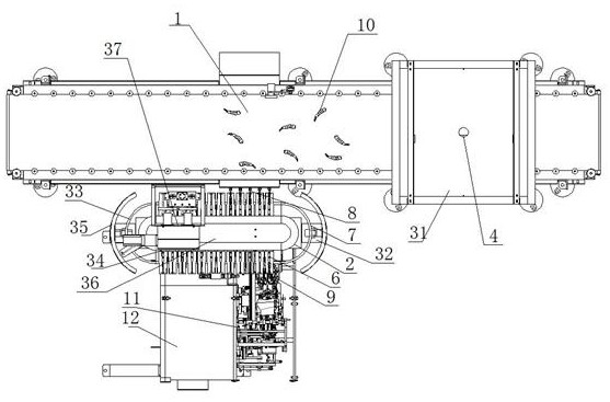
[0102] like Figure 7 shown, ( Figure 7 The manipulator is not shown in the figure 1 The manipulator arrangement structure diagram in ) is a feeding system of an automatic shrimp peeling machine, including a feeding tray 2, which is provided with a number of shrimp troughs 6, and the feeding tray 2 is provided with feeding The port 8 and the discharge port 9, the annular surface 7 formed by the movement trajectory of the shrimp trough 6 is parallel to the vertical plane (refer to the attached Figure 11 ), the feeding tray 2 includes at least a horizontal conveying section 13; it also includes a feeding conveyor belt 1 and a manipulator 3; the length of the horizontal conveying section 13 is greater than the length of the shell 12 of the shrimp peeling machine. The port 8 and the discharge port 9 are located on the same side of the feeding tray 2, the feeding port 8 is located on the side of the feeding tray 2 protruding from one end of the shell 12 of the shrimp peeling machine body, and the feeding conveyor belt 1 is located on the feeding tray 2. The feeding port 8 side of the tray 2, and the length direction of the shrimp slot 6 located at the feeding port 8 is perpendicular to the conveying direction of the feeding conveyor belt 1; The manipulator 3 placed in the shrimp trough 6 is installed above the feeding conveyor belt 1 and the feeding tray 2 .
[0103] In this technical solution, the horizontal conveying section 13 of the feeding tray 2 is extended beyond the length of the original shell 12 of the main body of the shrimp peeling machine, that is, this technical solution of this technical solution does not extend the existing vertical The structure of the feeding tray is greatly improved, only the conveying length of the horizontal conveying section 13 of the vertical feeding tray 2 is extended. In the existing shrimp peeling machine, such as Figure 11 It is indicated that the feeding tray 2 also includes a feeding port 8 and a discharging port 9, and the feeding port 8 and the discharging port 9 are located on the same side, which does not exceed the length of the shell 12 of the shrimp peeling machine body, because the A shrimp storage cavity 30 is provided on the casing 12 at the position of the feeding port 8 , which is convenient for the operator to place the raw shrimp 10 in the shrimp storage cavity 30 in the shrimp storage tank 6 at the feeding port 8 . If the existing feeding tray 2 is not improved, the feeding conveyor belt 1 and the manipulator 3 can only be arranged on the other side of the feeding tray 2 relative to the feeding port 8, which will make the manipulator 3 move the shrimp from the feeder. The stroke of picking on the feeding conveyor belt 1 and placing it in the shrimp trough 6 of the feeding tray 2 becomes longer, and the frequency of picking and placing of the manipulator 3 becomes lower. Refer to the manual attached Figure 12 , without changing the length of the horizontal conveying section 13 of the feeding tray 2, the moving stroke L3 of the manipulator is obviously larger than the moving stroke L4 of the manipulator in this technical solution, that is to say, under the same scene, the prior art The vertical feeding tray 2 will increase the moving stroke of the manipulator. However, this technical solution will shorten the moving stroke of the manipulator, so that the stroke of the manipulator 3 when placing the shrimp is shorter, the frequency of picking and releasing is faster, and the running speed of the feeding tray can be increased, so that the speed of the matching shrimp peeler can also be adjusted according to The speed of the feeding pan is correspondingly increased, making the shrimp peeling more efficient.
[0104] Further preferred technical solutions, with reference to the description attached figure 1, the manipulator 3 includes a visual collection device 4 and a manipulator action execution device 5, the visual collection device 4 is relatively independent from the manipulator action execution device 5, and the manipulator action execution device 5 is installed on the feeding tray 2 and the feeding conveyor belt. Above the 1, the visual acquisition device 4 is installed above the feeding conveyor belt 1 through the visual acquisition mounting frame 31, and along the conveying direction of the feeding conveyor belt 1, the visual acquisition device 4 is located in front of the manipulator action execution device 5;
[0105] The common manipulators on the market are equipped with visual acquisition devices, but generally the visual acquisition device is integrated in the execution end of the manipulator, and this technical solution specifically installs the visual acquisition device 4 and the manipulator action execution device 5 independently of each other. As for the feeding conveying system of this technical solution, the positioning and grasping ability of the manipulator 3 is required to be high, and the manipulator 3 must accurately grasp the specific position on the raw shrimp 10, otherwise the accurate positioning and placement of the shrimp cannot be completed. , this technical solution separates the visual acquisition device 4 and the manipulator action execution device 5 to ensure the accuracy of visual acquisition. Since the manipulator action execution end 5 will shake to a certain extent, if the visual acquisition device 4 is set at the execution end, there will be more interference in the collected image information, which is not conducive to the accurate positioning of the manipulator execution end. In the technical solution, the visual acquisition device and the action execution device of the manipulator are separately set, which can effectively ensure the accuracy of image acquisition and the stability of the positioning and grasping of the manipulator.
[0106] In a further preferred technical solution, the manipulator is a two-axis manipulator, a three-axis manipulator or an industrial robot. The illustration in this application only shows a three-axis manipulator, which does not mean that only three-axis manipulators can be implemented, two-axis manipulators can also be implemented, and industrial robots can also be implemented. The components are all capable of implementing the technical solution.
[0107] In a further preferred technical solution, the execution end of the manipulator is provided with a suction cup 14. In this technical solution, the raw shrimp can be grasped by means of suction, and the implementation is relatively simple. Figure 5 , including two suction cups 14, one of which is a positioning suction cup used as a positioning reference point for the manipulator to grab the shrimp. Positioning, grabbing and placing of raw shrimp 10 .
[0108] In a further preferred technical solution, in this embodiment, the execution end of the manipulator is provided with a gripper. Compared with the above-mentioned technical solution of sucking by the suction cup, the setting method of the gripper is one more gripper than that of suction. Action, but the effect is that the grip is firm, and the shrimp will not drop during the movement. The implementation of the solution by using the gripper can ensure the stability of the manipulator to grasp the shrimp, and prevent the shrimp from falling off the manipulator.
[0109] A further preferred technical solution, in this embodiment, refers to the appendix of the description. Figure 10 , the movement track of the shrimp trough is an ellipse, a circle or a ring formed by two straight lines and two circular arcs. The limitation of the movement trajectory of the shrimp trough is that the shrimp trough is required to always move horizontally to ensure that the shrimp tail is facing the outside at the position of the discharge port, and the stroke of the manipulator can be effectively controlled when grabbing the shrimp and placing the shrimp.
[0110] In this embodiment, for its working principle, take a raw shrimp 10 as an example. The raw shrimp 10 is conveyed by the feeding conveyor belt 1. During the conveying process, the visual acquisition device 4 collects the raw shrimp conveyed on the feeding conveyor belt 1. 10, and transmit the image information to the manipulator action execution device 5. During this process, the image information will be automatically converted into coordinate information and transmitted to the manipulator action execution device (this technology is the prior art of the manipulator's visual follow-up), The manipulator action execution device 5 grabs the raw shrimp 10 according to the transmitted image information, and then places the grabbed raw shrimp 10 in the shrimp placement slot 6 at the feeding port 8 of the feeding tray 2, the feeding tray 2 rotates, and the The shrimp trough 6 is rotated to the discharge port 9, and the shrimp clipping component of the shrimp peeling machine body 11 clamps the shrimp at the discharge port 9 and moves out of the feeding tray 2 to perform the shrimp peeling action.
Example Embodiment
[0111] Example 3
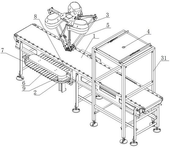
[0112] As another preferred embodiment of the present application, refer to the accompanying Figure 8 , the present embodiment provides a technical solution for the feeding and conveying method of an automatic shrimp peeling machine. The purpose of this technical solution is to solve the problems of poor automation, low feeding arrangement efficiency, Food safety and low efficiency of shrimp peeling. The technical solution adopts a manipulator for feeding, which can effectively realize the automatic feeding arrangement of raw shrimp, and can effectively improve the feeding arrangement efficiency of raw shrimp and the shrimp peeling efficiency of the shrimp peeling machine.
[0113] The technical solutions disclosed in this embodiment are as follows:
[0114] A feed conveying method for an automatic shrimp peeling machine, comprising the following steps:
[0115] Conveyor belt feeding step: the raw shrimp 10 is transported by the feeding conveyor belt 1 to the visual collection step;
[0116] The visual collection step: the image information on the feeding conveyor belt 1 is collected by the visual collection device 4, and the collected image information is sent to the manipulator grabbing code into the feeding step;
[0117] The manipulator grabs the code and enters the feeding step: the manipulator 3 receives the image information transmitted by the visual acquisition step, and according to the received image information, grabs the shrimp on the feeding conveyor belt 1, and places the grabbed shrimp on the feeding In the feed port 8 of the tray 2;
[0118] Shrimp storage and transportation steps in the feeding tray: The feeding tray 2 collects and stores the shrimp fed from the feeding port 8 , and rotates and transports it to the discharging port 9 .
[0119] In this technical solution, the processing process of the image information collected visually is the prior art, which generally includes the coordinate system of the visual collection device, the coordinate system of the manipulator, and the coordinate system of the target object. Convert the coordinate system of the target object to the coordinate system of the manipulator, and then convert the coordinate system of the target object to the coordinate system of the manipulator, so as to determine the coordinates of the target object, and the manipulator moves to the coordinates to grab the target object. In this process, the target object is Raw shrimp 10.
[0120] In this technical solution, the visual acquisition device 4 and the manipulator 3 exist independently, that is, the visual acquisition device 4 and the manipulator action execution device 5. The visual acquisition device 4 is separately arranged above the feeding conveyor belt 1, which can ensure the acquisition of The stability of the obtained image ensures the accuracy of the subsequent grasping and positioning of the robot.
[0121] The raw shrimp 10 is conveyed by the feeding conveyor belt 1. During the conveying process of the feeding conveyor belt 1, the visual acquisition device 4 collects the image of the raw shrimp 10 conveyed on the feeding conveyor belt 1, and recognizes the raw shrimp 10. The visual acquisition device 4 transmits the collected image information, raw shrimp position information and placement state information to the manipulator action execution device 5, and the manipulator 3 executes the manipulator action according to the received information. The execution end of 5 moves to the position of the raw shrimp 10, and adjusts the direction of the execution end according to the placement state of the raw shrimp 10. The execution end of the manipulator action execution device 5 grabs the raw shrimp 10 and moves the raw shrimp 10 to the feeding At the feeding port 8 position of the tray 2, the execution end of the manipulator action execution device 5 releases the grabbed raw shrimp 10, and the raw shrimp 10 automatically falls into the shrimp trough 6 at the feeding port 8 position, and the shrimp back 16 up.
[0122] In this technical solution, since the requirements for the placement of the raw shrimp 10 in the shrimp trough 6 are relatively strict, the manipulator is grabbing the raw shrimp 10 and placing the raw shrimp 10 in the shrimp trough. The requirements for positioning are also more stringent. If the placement position of the raw shrimp 10 in the shrimp placement tank 6 is not accurate, it will directly affect the working process and effect of the subsequent shrimp peeling step.
[0123] Preset the initial position information of the positioning reference point 22 on the robot arm 3 and the shrimp placement reference point 24 in the shrimp tank 6 in the feeding tray 2, and obtain the speed matching between the robot arm 3 and the feeding tray 2 according to the initial position information The visual acquisition device 4 collects the image data of the raw shrimp 10 on the feeding conveyor belt 1, and transmits the image data to the manipulator 3. The manipulator 3 receives the image data, and according to the image data, the execution end of the manipulator action execution device 5 is sent to the manipulator 3. The positioning reference point 22 on the top corresponds to the grasping reference point 23 of the raw shrimp 10; the manipulator 3 moves to grab the raw shrimp 10; after the execution end of the manipulator action execution device 5 locates and grabs the raw shrimp 10, the manipulator 3 moves according to the preset Move at a fixed speed, and place the raw shrimp 10 in the shrimp trough 6. At this time, the grasping reference point 23 of the raw shrimp 10 corresponds to the shrimp placing reference point 24 in the shrimp trough 6 to ensure that the raw shrimp 10 is located in the shrimp trough 6. The accuracy of the position in the groove 6 facilitates the smooth progress of the subsequent shrimp peeling process.
[0124] The shrimp placement reference point 24 of the shrimp placement trough 6 is formed by a positioning line 25 set in the shrimp placement slot. Generally, the second section of the shrimp tail is aligned with the positioning line.
[0125] When the execution end of the manipulator grabs the raw shrimp 10 and moves to the position of the feeding port 8 of the feeding tray 2, there are two positioning coordinate points, namely the first positioning coordinate point 20 and the second positioning coordinate point 21, and the execution end of the manipulator is at After grabbing the raw shrimp 10 and moving to the position of the feeding port 8 , the selection of the positioning coordinate point is determined by the state information of the raw shrimp 10 on the feeding conveyor belt 1 .
[0126] The specific performance is as follows: the structural features of the raw shrimp 10 include a shrimp back 16, a shrimp belly 19, a first side 17 and a second side 18. During the conveying process of the raw shrimp 10 on the feeding conveyor belt 1, they are all lying on the feeding conveyor belt. On the material conveyor belt 1, that is, the first side faces 17 or the second side 18 is upward, if the first side 17 is upward, the execution end of the manipulator 3 is grabbed on the first side 17, with the first side 17 facing Grab and move the raw shrimp 10 in the upper posture, when placed, the manipulator 3 corresponds to the first positioning coordinate point 20, the manipulator 3 moves to the first positioning coordinate point 20 to release the raw shrimp 10, and the second side 18 of the raw shrimp 10 is first connected to the The side surface of the shrimp trough 6 (the second shrimp trough plate 27) is in contact, and under the guiding action of the side, it slides into the shrimp trough 6, and when it slides down to the bottom of the prawn trough 6, the shrimp back 16 is formed. , The shrimp belly 19 is facing down, and the two side plates (the first shrimp tank plate 26 and the second shrimp tank plate 27 ) of the shrimp tank 6 are in close contact with the first side 17 and the second side 18 of the raw shrimp 10 respectively. If the state of the raw shrimp 10 on the feeding conveyor belt 1 is that the second side 18 faces upwards, the positioning point moved by the manipulator 3 after grabbing is the second positioning coordinate point 21 . After the raw shrimp 10 is released, the The first side 17 is in contact with the other side of the shrimp trough 6 (the first shrimp trough plate 26 ), and under the guidance of this side, the raw shrimp 10 slides down into the shrimp trough 6 , and then slides down to the prawn trough 6 . When the bottom is formed, the shrimp back 16 is upward, the shrimp belly 19 is downward, and the two side plates (the first shrimp trough plate 26 and the second shrimp trough plate 27) of the shrimp trough 6 are formed to be close to the first side of the raw shrimp 10 respectively. 17 and the state of the second side 18.
[0127] The three-dimensional coordinate system is established on the basis of the feeding tray 2, then the plane above the shrimp trough 6 is the XY coordinate system, the length direction of the shrimp trough 6 is the Y axis, and the moving direction of the shrimp trough 6 is the X axis, then the first Between the positioning coordinate point 20 and the second positioning coordinate point 21, the Y-axis position is the same, and the X-axis position is different.
[0128] When the raw shrimp 10 is conveyed on the feeding conveyor belt 12, the position and status information of the raw shrimp 10 on the feeding conveyor belt 1 are collected by the visual acquisition device 4, and the status information includes the direction of the shrimp tail 28, the first shrimp The orientation of the side 17 and the second side 18, the manipulator 3 rotates correspondingly according to the information collected by the visual acquisition device 4, to ensure that the positioning reference point 22 of the execution end of the manipulator corresponds to the grab reference point 23 on the raw shrimp 10 to ensure that the raw material is placed After the shrimps 10 are placed, the shrimp tails 28 of the raw shrimps 10 are exposed to the shrimp trough 6, and the directions are the same.
[0129] In the step of storing shrimp in the feeding tray, the annular surface 7 formed by the movement trajectory of the shrimp trough 6 for placing the raw shrimp 10 on the feeding tray 2 is parallel to the horizontal plane, and the raw shrimp 10 is moved from the feeding conveyor belt 1 by the robot 3 Grab it and place it in the shrimp trough 6 located at the feeding port 8 on one side of the feeding tray 2 . There are 9 feed ports.
[0130] In the step of storing shrimp in the feeding tray, the annular surface 7 formed by the movement trajectory of the shrimp trough 6 for placing the raw shrimp 10 on the feeding tray 2 is parallel to the vertical plane, and the feeding tray 2 includes at least one horizontal conveying section 13. , the raw shrimp 10 is grabbed from the feeding conveyor belt 1 by the manipulator 3, and placed in the shrimp trough 6 at the feeding port 8 on the side of the feeding tray 2, and the prawn trough 6 continues to move forward horizontally, moving To the discharge port 9 on the same side as the feed port 8.
PUM


Description & Claims & Application Information
We can also present the details of the Description, Claims and Application information to help users get a comprehensive understanding of the technical details of the patent, such as background art, summary of invention, brief description of drawings, description of embodiments, and other original content. On the other hand, users can also determine the specific scope of protection of the technology through the list of claims; as well as understand the changes in the life cycle of the technology with the presentation of the patent timeline. Login to view more.