Special take-up device frame for high-voltage test wire

A high-voltage test and wire take-up technology, which is applied in the direction of conveying filamentous materials, thin material handling, transportation and packaging, etc., can solve problems such as waste of energy, cable entanglement, and inconvenient take-up, so as to achieve convenient and safe work and prevent Electric shock, the effect of increasing the service life

Pending Publication Date: 2021-01-05
STATE GRID SHANDONG ELECTRIC POWER +1
View PDF8 Cites 0 Cited by
  • Summary
  • Abstract
  • Description
  • Claims
  • Application Information

AI Technical Summary

Problems solved by technology

[0004] The purpose of the present invention is to provide a special wire take-up frame for high-voltage test lines, so as to solve the problems that the high-voltage wire take-up equipment in the background technology is inconvenient to take up the wires, it often takes a long time, wastes energy, and the problems such as cable entanglement will occur when the wires are taken up.

Method used


Image

  • Special take-up device frame for high-voltage test wire
  • Special take-up device frame for high-voltage test wire
  • Special take-up device frame for high-voltage test wire

Examples


Embodiment 1

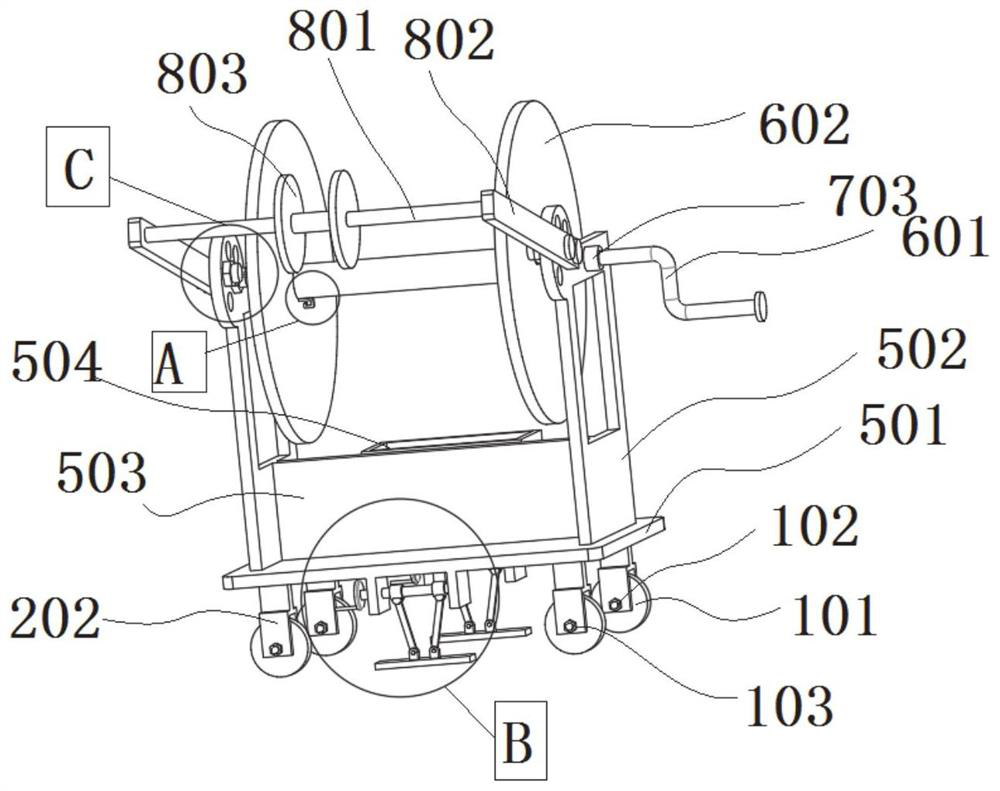
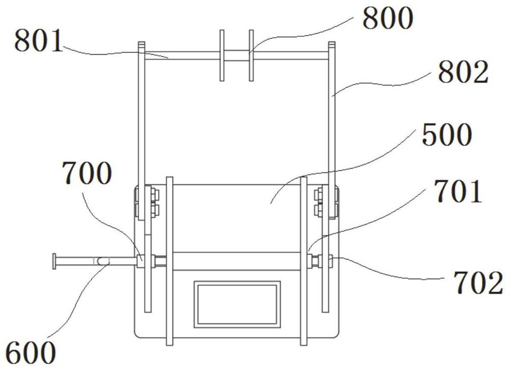
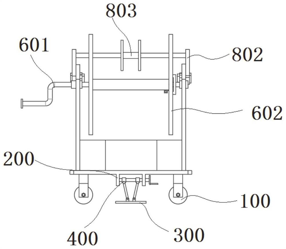
[0032] see Figure 1-6 As shown, the present invention is a special wire take-up rack for high-voltage test lines, including a moving device 100, a fixing device 200, a stabilizing device 300, a connecting device 400, a supporting device 500, a wire taking-up device 600, a limiting device 700 and a preventing device 800, The moving device 100 includes a wheel shaft 102, the fixing device 200 includes a protruding block 201, a shaft plate 202, and a rotating shaft 203, a shaft hole is provided on one side of the shaft plate 202, the wheel shaft 102 is rotatably matched with the shaft hole, and the stabilizing device 300 includes a connecting rod 303, The connection device 400 includes a slider 401 and a rotating block 402. The slider 401 is arranged on the outer surface of the rotating shaft 203. One side surface of the rotating block 402 is welded to one end of the rotating shaft 203. The supporting device 500 includes a bottom plate 501, a supporting plate 502, and a protrudin...

Embodiment 2

[0042] see Figure 1-6 As shown, the present invention is a special wire take-up frame for high-voltage test line. Its use method and working principle are as follows: when working, the device is moved to the set working position through the wheel 101, and after reaching the working position, the handle 403 is rotated to drive the rotation The block 402 moves to make the rotating shaft 203 rotate. The rotating shaft 203 is provided with threads, and the slider 401 is also provided with threads. By rotating, the sliding block 401 and the rotating shaft 203 move in the opposite direction, thereby driving the connecting rod 303 to move. 303 drives the compression plate 301 to compress, so that the device is fixed on the ground and does not shake during work. Then one end of the cable is wound on the hook 603, and the cable is arranged on the movable pulley 803 to prevent it from being entangled. Rotate the manual lever 601, thereby driving the reel 602 to rotate, the limit block ...


PUM


Abstract

The invention discloses a special take-up device for a high-voltage test wire, and relates to the technical field of high-voltage equipment. The device comprises a moving device, a fixing device, a stabilizing device, a connecting device, a supporting device, a take-up device body, a limiting device and a preventing device, the moving device comprises a wheel shaft, the fixing device comprises a protruding block, a shaft plate and a rotating shaft, the connecting device comprises a sliding block and a rotating block, and the supporting device comprises a bottom plate and a supporting plate. The limiting device comprises a limiting block, a bearing, a shaft sleeve and a fixing screw, the preventing device comprises a connecting plate, the special take-up device can be moved to a working position through wheels, the protruding block is adopted to facilitate pressing of a pressing plate, and therefore the special take-up device is fixed, is prevented from sliding and cannot slide, and oneend of a cable is fixed through a hook and a wire coil. Manual pulling is not needed, and the cable can slide down through a movable pulley, so that the direction of the cable is limited, and windingis avoided.

Description

technical field [0001] The invention belongs to the technical field of high-voltage equipment, in particular to a special wire take-up frame for a high-voltage test line. Background technique [0002] Lines usually refer to transmission lines that carry voltages above 10kV (including 10kV). High voltage usually does not include 1000V. There may be problems such as leakage and winding when charging, which greatly troubles people. [0003] The existing high-voltage wire take-up equipment is inconvenient to take up the wire, it often takes a long time, wastes energy, and there will be shortcomings such as cable entanglement when taking up the wire. For this reason, we propose a special wire take-up frame for high-voltage test lines. Contents of the invention [0004] The purpose of the present invention is to provide a special wire take-up frame for high-voltage test lines, so as to solve the problems of inconvenient take-up in the high-voltage take-up equipment in the backg...

Claims


Application Information

Patent Timeline
Patent Type & Authority Applications(China)
IPC IPC(8): B65H54/40B65H54/54
CPCB65H54/40B65H54/54B65H2701/34
Inventor 杨凯强焦伟刘成华李小龙盖磊徐再兴王雨秋赵祥龙陈涛曾会师李晗徐俊玲
Owner STATE GRID SHANDONG ELECTRIC POWER
Why Eureka
Try Eureka