
Dust removal device of tamping protection mechanism for rapid tamping machine

A technology of protective mechanism and dust removal device, which is applied in the direction of combined device, soil protection, infrastructure engineering, etc., and can solve problems that affect the sight and breathing health of operators, and dust is easy to fly, etc.

Active Publication Date: 2021-01-05
新疆隆泉建设集团有限公司
View PDF7 Cites 2 Cited by
  • Summary
  • Abstract
  • Description
  • Claims
  • Application Information

AI Technical Summary

Problems solved by technology

[0002] Building is a kind of space for people to live and use that people use soil, brick, tile, stone, wood; (reinforced concrete, profiles) and other building materials, such as residences, bridges, factories, gymnasiums, caves, water towers, Temples, etc. At present, in addition to large-scale tamping machines, traditional tamping machines are relatively common on construction sites, but when the tamping machine is used on dry soil, the dust is easy to fly, which affects the sight and breathing health of the operators. For this reason, We propose a dust removal device for the tamping protection mechanism of the rapid tamping machine

Method used


Image

  • Dust removal device of tamping protection mechanism for rapid tamping machine
  • Dust removal device of tamping protection mechanism for rapid tamping machine
  • Dust removal device of tamping protection mechanism for rapid tamping machine

Examples


Embodiment Construction

[0024] The following will clearly and completely describe the technical solutions in the embodiments of the present invention with reference to the accompanying drawings in the embodiments of the present invention. Obviously, the described embodiments are only some, not all, embodiments of the present invention. Based on the embodiments of the present invention, all other embodiments obtained by persons of ordinary skill in the art without making creative efforts belong to the protection scope of the present invention.

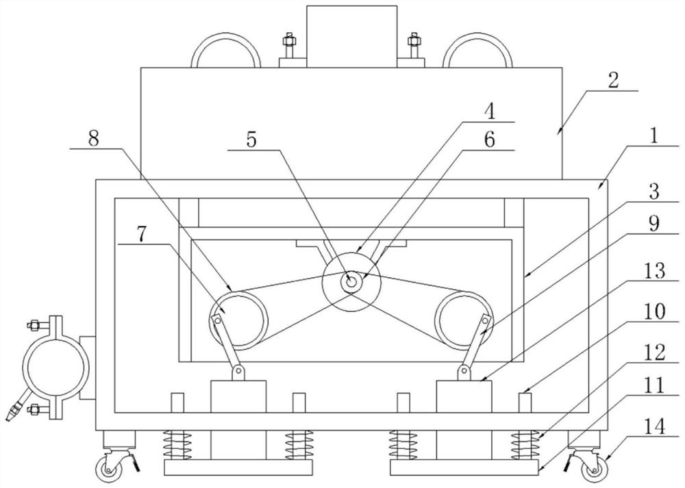
[0025] The invention provides a technical solution: a dust removal device for a tamping protection mechanism for a fast tamping machine, please refer to figure 1 , including box 1, moving wheels 14 are installed at the four corners of the bottom of box 1, dust suppression assembly 2 is installed on the top of box 1, a connecting frame is welded on the inner wall of the top of box body 1, an installation shell 3 is welded on the bottom of the connecting frame, a...


PUM


Abstract

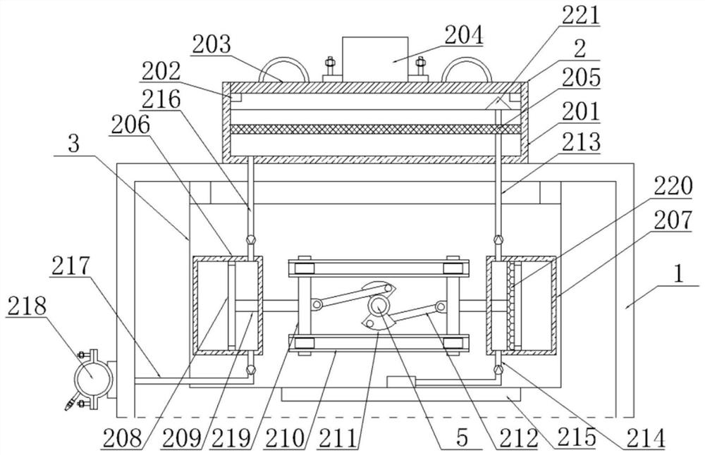
The invention discloses a dust removal device of a tamping protection mechanism for a rapid tamping machine. The dust removal device comprises a box body, the outer walls of cylinder bodies are fixedly sleeved with a front transmission belt wheel and a rear transmission belt wheel, the transmission belt wheels are located on the outer side of a mounting shell, a driving motor is arranged on the inner sides of the cylinder bodies on the left side and the right side, the transmission belt wheels and a belt wheel are connected through belts, and columns are installed on the outer walls of the front sides and the rear sides of the cylinder bodies correspondingly. External clean water is used for dust falling, specifically, a rotating shaft drives a fan-shaped plate to rotate, the fan-shaped plate rotates along with the rotating shaft and can drive a movable rod piece to move, sliding plates slide left and right in sliding rails, when a piston plate on the left side is driven to move leftwards, clean water in an inner cavity of a connecting water cylinder can be squeezed out through a one-way water outlet pipe, and finally the clean water is sprayed out through a water distribution pipeand an atomizing nozzle, soil in the advancing direction of a tamping device can be wetted, dust falling work is achieved, when the left piston plate moves rightwards, negative pressure is generated,the clean water in an inner cavity of a water tank is pumped into the connecting water cylinder through a one-way water inlet pipe, and water is supplemented in time.

Description

technical field [0001] The invention relates to the technical field of foundation tamping machines, in particular to a dust removal device for a tamping protection mechanism for a fast tamping machine. Background technique [0002] Building is a kind of space for people to live and use that people use soil, brick, tile, stone, wood; (reinforced concrete, profiles) and other building materials, such as residences, bridges, factories, gymnasiums, caves, water towers, Temples, etc. At present, in addition to large-scale tamping machines, traditional tamping machines are relatively common on construction sites, but when the tamping machine is used on dry soil, the dust is easy to fly, which affects the sight and breathing health of the operators. For this reason, We propose a dust removal device for a tamping protection mechanism for a fast tamping machine. Contents of the invention [0003] The object of the present invention is to provide a dust removal device for a tamping...

Claims


Application Information

Patent Timeline
IPC IPC(8): E02D3/046E02D3/074B01D50/00
CPCE02D3/046E02D3/074B01D50/60
Inventor 祝丽娟
Owner 新疆隆泉建设集团有限公司
Learn More