LED energy-saving lamp capable of saving energy and achieving light-operated illumination

A technology for lamps and lamp holders, which is applied to components of lighting devices, damage prevention measures for lighting devices, lighting devices, etc. It can solve the problems of reduced imaging clarity and dimming of luminosity, and achieves accelerated aging and increased friction The effect of increasing the force and increasing the contact area

Inactive Publication Date: 2021-01-05
常州菲尼霖建筑装潢有限公司
View PDF0 Cites 0 Cited by
  • Summary
  • Abstract
  • Description
  • Claims
  • Application Information

AI Technical Summary

Problems solved by technology

[0002] In order to reduce power consumption during the use of LED lamps, LED lamps are combined with light control sensors. The sensor automatically senses the lightness of the outside world and cuts off and supplies the bulb current in time. Due to the various brightness of LED lamps, it is widely used in studios. It is widely used in LED lamps; in the prior art, when using LED lamps, flashlights are often used in the process of photography. When the flashlight suddenly illuminates, the sensor cuts off the current in time, and the bulb stops emitting light, resulting in dimming of the imaging environment of the camera. , and the imaging resolution is reduced

Method used


Image

  • LED energy-saving lamp capable of saving energy and achieving light-operated illumination
  • LED energy-saving lamp capable of saving energy and achieving light-operated illumination
  • LED energy-saving lamp capable of saving energy and achieving light-operated illumination

Examples


Embodiment 1

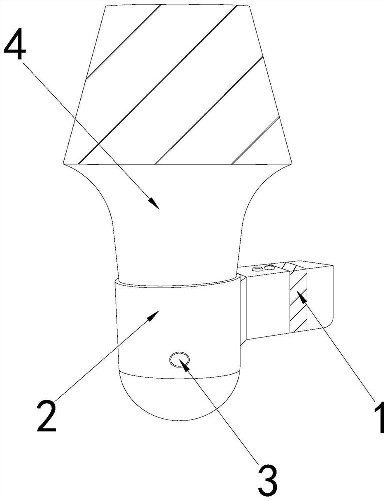
[0025] as attached figure 1 to attach Figure 5 Shown:

[0026] The invention provides an LED energy-saving lamp capable of energy-saving and light-controlled lighting. Its structure includes a controller 1, a lamp holder 2, an induction block 3, and a lamp body 4. 3 is arranged on the front of the lamp holder 2, and the lamp body 4 is vertically fixed on the top of the lamp holder 2.

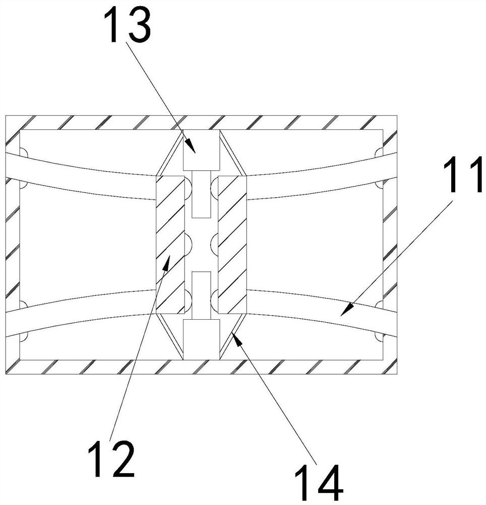
[0027] The controller 1 is provided with a wire 11, a conductive sheet 12, a push block 13, and a conduit 14. The conductive sheet 12 is installed inside the controller 1, and the conductive sheet 11 runs through both sides of the controller 1 and is connected to the conductive sheet 12. The push blocks 13 are respectively fixed on the upper and lower sides of the controller 1 and located between the conductive sheets 12 , and the conduits 14 are respectively arranged between the two sides of the bottom surface of the push block 13 and the wires 11 .

[0028] Wherein, the push block 13 is pr...

Embodiment 2

[0034] as attached Figure 6 to attach Figure 7 Shown:

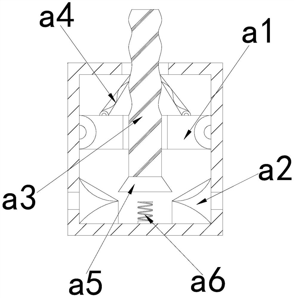
[0035]Wherein, the support bar a1 is provided with a support block r1, a clamping block r2, and a bracket r3, the clamping block r2 is installed on the inner wall of the support bar a1 through the support block r1, and the bracket r3 is located at both ends of the clamping block r2 and Between the inner walls of the support rods a1, there are three clamping blocks r2, which are in the shape of a concave arc, which is conducive to increasing the contact area with the outer wall of the conductive tube a3, increasing the friction force, and slowing down the reset speed of the conductive tube a3.

[0036] Wherein, the clamping block r2 is provided with a top plate t1, an air hole t2, an air cavity t3, a pressure rod t4, and a return spring t5, the top plate t1 is located on the top of the clamping block r2, and the air hole t2 runs through the upper and lower surfaces of the top plate t1, so The air cavity t3 is arranged ...


PUM


Abstract

The invention discloses an LED energy-saving lamp capable of saving energy and achieving light-operated illumination. The lamp structurally comprises a controller, a lamp holder, an induction block and a lamp body, due to the fact that a current is cut off in time by an instant inductor when a flash lamp suddenly illuminates, a bulb stops emitting light; and with the change of the current around aconducting strip through a push block, the conductive tube moves up and down to be in contact with a conductive sheet to electrify the lamp holder, so that the current between the lamp holders can beimmediately cut off, the bulb can continuously emit light for a period of time to be extinguished, the imaging environment luminosity of the camera is not changed, and the imaging definition is keptnormal; because the conductive tube is affected by too fast reduction of the own gravity, the current of the lamp holder becomes intermittent to accelerate aging; a clamping block in a supporting rodis movably matched with the conductive tube, so that the contact area between the clamping block and the outer wall of the conductive tube is increased, the friction force is increased, the moving speed of the conductive tube is limited, slow moving of the conductive tube is facilitated, the lamp holder is protected, and the service life of the lamp holder is prolonged.

Description

technical field [0001] The invention belongs to the field of LED lamps, and more specifically relates to an LED energy-saving lamp capable of energy-saving light-controlled lighting. Background technique [0002] In order to reduce power consumption during the use of LED lamps, LED lamps are combined with light control sensors. The sensor automatically senses the lightness of the outside world and cuts off and supplies the bulb current in time. Due to the various brightness of LED lamps, it is widely used in studios. It is widely used in LED lamps; in the prior art, when using LED lamps, flashlights are often used in the process of photography. When the flashlight suddenly illuminates, the sensor cuts off the current in time, and the bulb stops emitting light, resulting in dimming of the imaging environment of the camera. , and the imaging resolution is reduced. Contents of the invention [0003] In order to solve the problem that the brightness of the above-mentioned LED...

Claims


Application Information

Patent Timeline
Patent Type & Authority Applications(China)
IPC IPC(8): F21S8/00F21V15/00F21V23/02F21V23/06G03B15/02F21Y115/10
CPCF21S8/00F21V15/00F21V23/02F21V23/06F21Y2115/10G03B15/02
Inventor 王晓明
Owner 常州菲尼霖建筑装潢有限公司
Why Eureka
Try Eureka