Double-wall cooling structure of hyperbolic turbulent flow column with air film holes

A cooling structure, air film hole technology, applied in the direction of combustion methods, lighting and heating equipment, continuous combustion chamber, etc., can solve the problems of high pressure loss of cold air, large internal flow resistance, etc., to reduce damage, weaken flow resistance, The effect of weight reduction

Active Publication Date: 2021-01-05
NORTHWESTERN POLYTECHNICAL UNIV
View PDF9 Cites 11 Cited by
  • Summary
  • Abstract
  • Description
  • Claims
  • Application Information

AI Technical Summary

Problems solved by technology

Although this structure can achieve a better heat exchange effect, the internal flow resistance is relatively large, and the pressure loss of the cold air is large.

Method used


Image

  • Double-wall cooling structure of hyperbolic turbulent flow column with air film holes
  • Double-wall cooling structure of hyperbolic turbulent flow column with air film holes
  • Double-wall cooling structure of hyperbolic turbulent flow column with air film holes

Examples


Embodiment

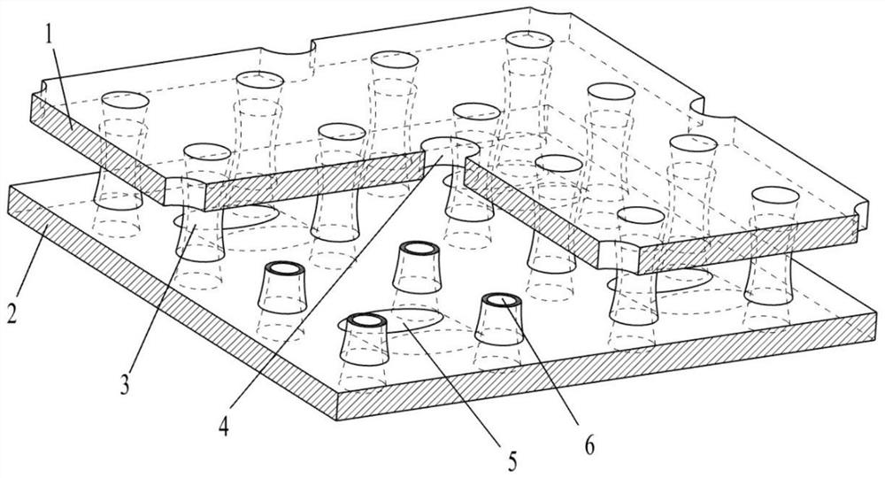
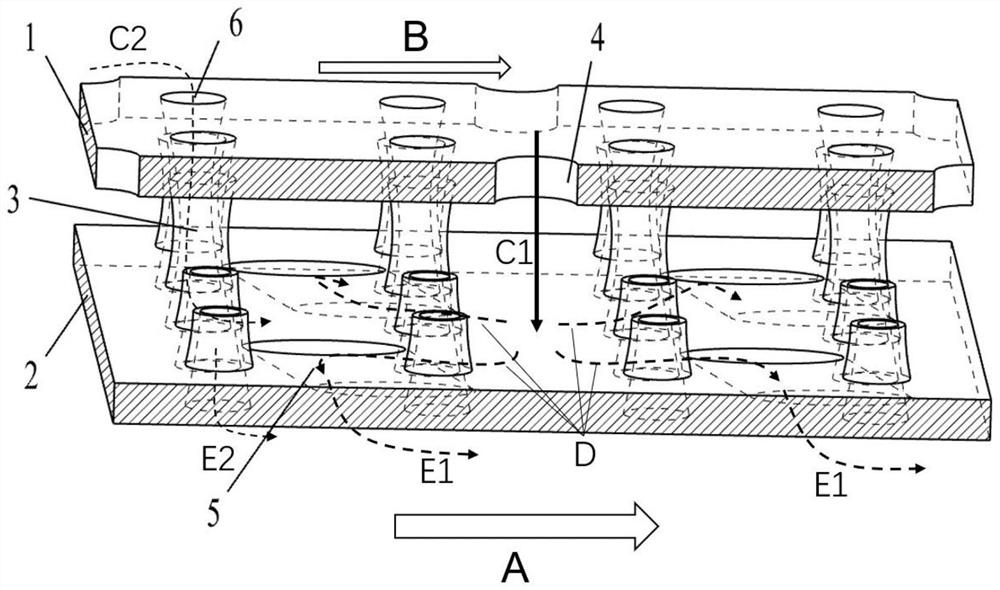
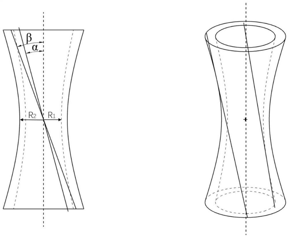
[0034] This embodiment is a double-walled cooling structure with a hyperbolic spoiler column with air film holes. The thickness of impact orifice plate and air film orifice plate is 1.5mm. Impact hole diameter D f 3mm, forming an angle of 90° with the impact orifice plate, the impact distance is 4mm, and the hole spacing and hole row spacing are both 2.7D f . The air film hole and the airflow in the inner channel form a 30° inclination angle, and the diameter of the air film hole is D f 3mm, hole spacing and hole spacing are both 2.7D f . Air film holes and impact holes are arranged alternately; hyperbolic spoiler columns are arranged between air film holes and impact holes, and air film hole channels in hyperbolic spoiler columns are separated by a certain distance R from the axis of the columns. 1 And the straight line forming a certain angle α on the axis is rotated around the axis of the column to obtain, R 1 Take it as 0.25D f , α is taken as 15°; the outer wall of...


PUM


Abstract

The invention discloses a double-wall cooling structure of a hyperbolic turbulent flow column with air film holes, and belongs to the field of gas turbine engines. The double-wall cooling structure comprises an air film pore plate, an impact pore plate and a plurality of hyperbolic turbulent flow columns with the air film holes arranged between the air film pore plate and the impact pore plate toform a double-wall cooling structure, impact holes are formed in the impact pore plate and are axially vertical to the impact pore plate, the air film holes are formed in the air film pore plate, theaxial direction of the air film holes and the duct airflow direction form a 20-90 degrees inclination angle, the impact holes and the air film holes are periodically arranged in a staggered manner along the airflow direction, the hyperbolic turbulent flow columns with the air film hole are hyperbolic turbulent flow columns with inner air film holes, and cooling air flows are led into one side of afuel gas duct from one side of a cold air duct through the air film holes in the hyperbolic turbulent flow columns. Compared with a traditional structure, the cold air attaching effect is better, andthe on-way cooling effect is greatly improved.

Description

technical field [0001] The invention belongs to the field of gas turbine engines, and in particular relates to a double-wall cooling structure of a hyperbolic spoiler column with gas film holes. Background technique [0002] During short-distance take-off, climb, and fast maneuvering stages, military aircraft often use afterburner to reburn the exhaust after the turbine to meet the demand for extra large thrust in a short period of time. The booster located between the turbine and the tail nozzle Force combustors are used to implement the above goals. However, since the inlet temperature of the afterburner is as high as 950-1000K, the gas temperature after re-ignition in the afterburner can be as high as 2050K-2100K, or even higher, and the afterburner is usually turned on and off in a short period of time, so Not only cooling at extremely high temperatures must be considered, but also thermal stress and thermal deformation due to temperature distribution and changes. In a...

Claims


Application Information

Patent Timeline
Patent Type & Authority Applications(China)
IPC IPC(8): F23R3/00
CPCF23R3/00F23R3/002F23R2900/03042F23R2900/03043
Inventor 朱惠人徐志鹏郭涛张丽许卫疆李鑫磊周道恩
Owner NORTHWESTERN POLYTECHNICAL UNIV
Why Eureka
Try Eureka