[0030]The principles and features of the present invention will be described below with reference to the accompanying drawings. The examples cited are only used to explain the present invention, and are not used to limit the scope of the present invention.
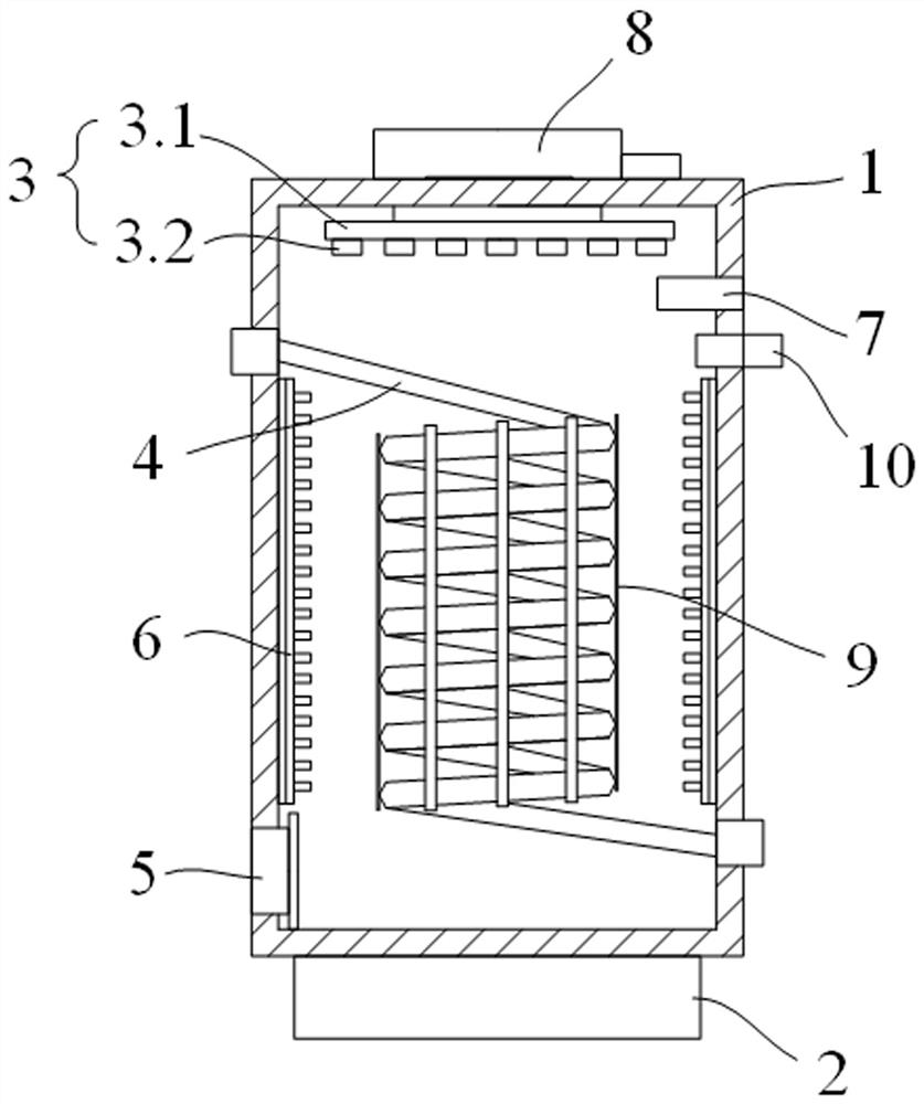
[0031]Such asfigure 1 withfigure 2As shown, an industrial heat dissipating tower includes a heat dissipating tower 1 and a base 2. The heat dissipating tower 1 is fixed on the upper end of the base 2; the heat dissipating tower 1 is provided with a water spray device 3, a heat dissipation pipe 4, and an air exhaust Machine 5, the water spray device 3 is placed at the upper end of the heat dissipation tower 1, and is fixedly connected to the inner top of the heat dissipation tower 1;
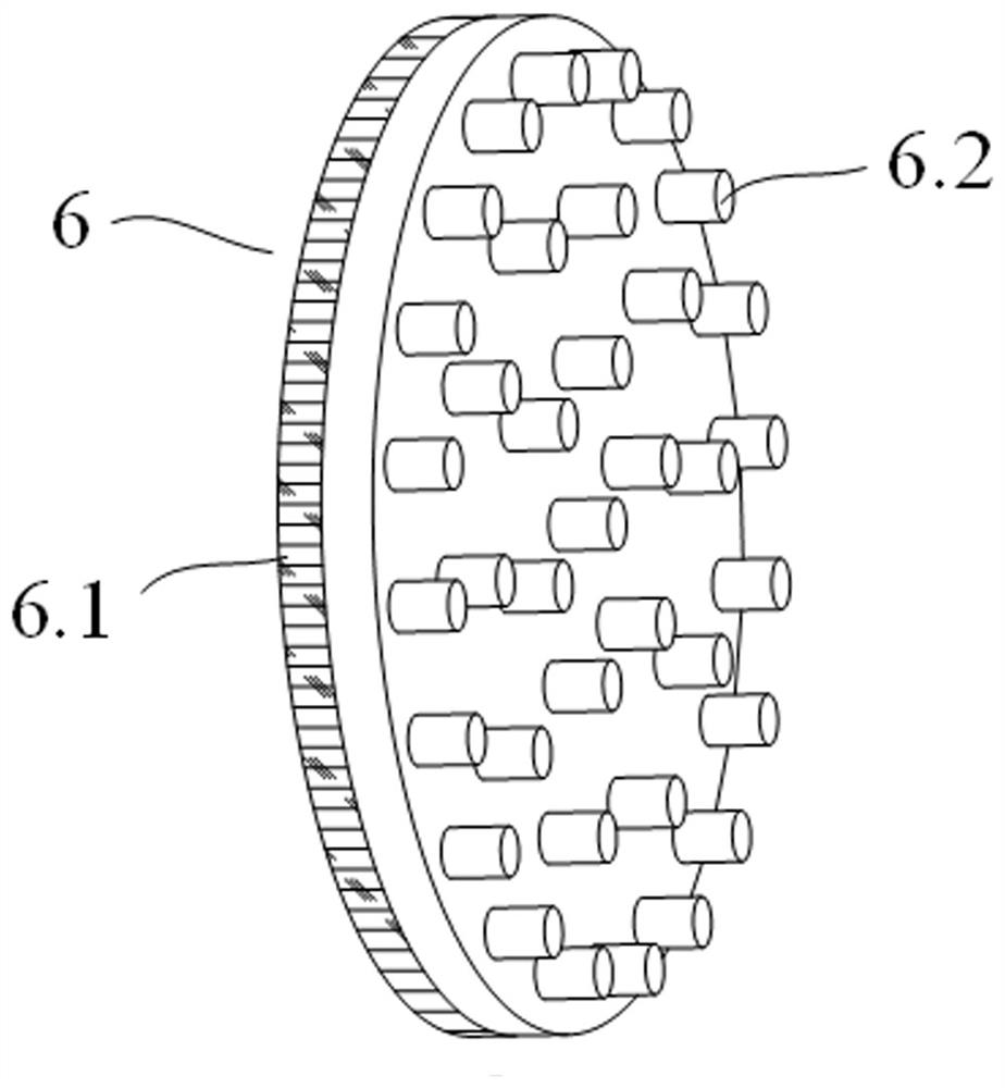
[0032]The heat-conducting devices 6 are provided on the side walls at both ends of the heat dissipation tower 1, and the two heat-conducting devices 6 are respectively fixedly connected to the side walls of the heat dissipation tower 1;
[0033]The radiating pipe 4 is placed in the radiating tower 1 in a spiral shape, and the upper end of the radiating pipe 4 extends to the upper end of the heat conducting device 6, and passing through the side wall of the radiating tower 1 to introduce airflow or Liquid; the lower end of the heat dissipation pipe 4 extends to the lower end of the other heat conduction device 6, and passes through the side wall of the heat dissipation tower 1 to discharge airflow or liquid;
[0034]The exhaust fan 5 is placed at the inner bottom of the heat dissipation tower 1 and is fixedly connected to the side wall of the heat dissipation tower 1, and the exhaust fan 5 exhausts the airflow in the heat dissipation tower 1;
[0035]An air duct 7 is provided on the side wall of the upper end of the heat dissipation tower 1, and one end of the air duct 7 extends into the heat dissipation tower 1 and closely adheres to the inner wall of the heat dissipation tower 1; the air duct 7 Introduce an external airflow, and introduce the airflow into the heat dissipation tower 1 for swirling;
[0036]The side wall of the upper end of the heat dissipation tower 1 is also provided with an ultrasonic generator 10, and the generating end of the ultrasonic generator 10 extends into the heat dissipation tower 1; the ultrasonic generator 10 is located in the ultrasonic generator 10 The lower end.
[0037]The gas or liquid that needs to be dissipated is introduced into the radiating pipe 4, and the gas or liquid that needs to be radiated is radiated in the process of flowing in the radiating pipe 4, and then flows out through the lower end of the radiating pipe 4;
[0038]During the heat dissipation of the gas or liquid that needs to be dissipated in the radiator pipe 4, the water spray device 3 sprays water on the radiator pipe 4 to cool the radiator pipe 4 to realize rapid heat dissipation of the gas or liquid in the radiator pipe 4; the water forms water after being heated The vapor diffuses to the heat-conducting device 6, and the heat-conducting device 6 conducts the heat of the water, reduces the temperature drop in the heat dissipation tower 1, thereby promoting the rapid heat dissipation of gas or liquid;
[0039]At the same time, the exhaust fan 5 draws air into the heat dissipation tower 1 to reduce the air pressure in the heat dissipation tower 1; the air guide tube 7 is used to introduce the external air flow, and the air flow swirls in the heat dissipation tower 1, and the air flow disperses the water flow from the water spray device 3 to form Water droplets; the ultrasonic generator 10 is then used to emit ultrasonic waves to the water droplets, which impacts the water droplets and disperses the water droplets, forming a mist in the cooling tower 1 to wrap the radiating pipe 4, and the radiating pipe 4 heats up more comprehensively or efficiently; the water mist after the heat is heated Under the action of the air flow, it is discharged by the exhaust fan 5; in addition, the water forms water vapor after being heated on the heat dissipation pipe 4, and the water vapor and the water mist are fully mixed to accelerate the heat dissipation efficiency.
[0040]In this embodiment, water is sprayed to the heat dissipation pipe 4, so that the gas or liquid in the heat dissipation pipe 4 is quickly dispersed; the airflow is also introduced to disperse the water flow, and then the ultrasonic generator 10 is used to impact, so that water mist is formed in the heat dissipation tower 1, and the water mist is used to The gas or liquid in the heat pipe 4 dissipates heat, the heat dissipation area is large, and the heat dissipation efficiency is improved.
[0041]In the above embodiment, the upper end of the heat dissipation tower 1 is provided with a water tank 8 which is fixedly connected to the heat dissipation tower 1; the water tank 8 passes downward through the top of the heat dissipation tower 1 and the The water spray device 3 is connected.
[0042]The water tank 8 stores water and delivers water into the water spray device 3 so that the water spray device 3 performs stable water spray.
[0043]In the above embodiment, the water spray device 3 includes a spray disc 3.1 and a plurality of spray heads 3.2, the spray disc 3.1 is placed on the top of the inner side of the heat dissipation tower 1, and the spray disc 3.1 and the inner side of the heat dissipation tower 1 The top is fixedly connected; a plurality of the spray heads 3.2 are fixedly arranged at the lower end of the spray plate 3.1 and communicate with the spray plate 3.1; the spray plate 3.1 communicates with the water tank 8 through a water pipe.
[0044]The spray plate 3.1 introduces the water in the water tank 8 and sprays the water through multiple spray nozzles 3.2, so that the water is evenly sprayed to the heat dissipation tower 1, which facilitates the impact of the airflow on the water and improves the heat dissipation efficiency of the heat dissipation pipe 4.
[0045]In the above-mentioned embodiment, a plurality of radiating fins 9 are arranged in the middle of the heat dissipation pipe 4, and the plurality of radiating fins 9 are arranged in sequence along the circumferential direction of the middle of the heat dissipation pipe 4. The spacing between them is consistent.
[0046]The multiple radiating fins 9 can accelerate the heat dissipation in the radiating pipe 4, and the water mist can contact the radiating pipe 4 and the multiple radiating fins 9, which can increase the heat dissipation area and improve the heat dissipation efficiency.
[0047]In the above embodiment, the heat conduction device 6 includes a heat dissipation plate 6.1 and a plurality of heat dissipation columns 6.2. The heat dissipation plate 6.1 is vertically fixed on the side wall of the heat dissipation tower 1; the plurality of heat dissipation columns 6.2 are arranged side by side On the heat dissipation plate 6.1, one end of each heat dissipation column 6.2 is fixedly connected to the heat dissipation plate 6.1, and the other end of each heat dissipation column 6.2 extends into the heat dissipation tower 1.
[0048]After the multiple heat dissipation columns 6.2 are in contact with the water vapor, the contact area can be increased, and the heat of the water vapor can be quickly discharged through the heat dissipation plate 6.1, thereby improving the heat dissipation efficiency.
[0049]In the above embodiment, the air duct 7 extends into the end of the heat dissipation tower 1, and its inner diameter gradually decreases.
[0050]The inner diameter of the end of the air guide tube 7 is gradually reduced, which can effectively increase the air pressure of the air flow at the air guide tube 7, enhance the impact strength of the air flow on the water, and make the water droplets more uniform and efficient.
[0051]The above descriptions are only preferred embodiments of the present invention and are not intended to limit the present invention. Any modification, equivalent replacement, improvement, etc. made within the spirit and principle of the present invention shall be included in the protection of the present invention. Within range.