
Redundant configuration inertial measurement unit biaxial rotation modulation method

An inertial measurement unit, redundant configuration technology, applied in measurement devices, navigation through velocity/acceleration measurement, instruments, etc., can solve the problems of reduced modulation effect, inability to form analysis models, etc., to improve modulation effect and improve navigation accuracy Effect

Active Publication Date: 2021-01-05
PLA PEOPLES LIBERATION ARMY OF CHINA STRATEGIC SUPPORT FORCE AEROSPACE ENG UNIV
View PDF6 Cites 5 Cited by
  • Summary
  • Abstract
  • Description
  • Claims
  • Application Information

AI Technical Summary

Problems solved by technology

According to public information, only Cheng Jianhua’s team at home and abroad has conducted relevant preliminary research on the rotation modulation technology of redundant inertial navigation (Cheng Jianhua et al. Two-axis rotation modulation method for redundant configuration of strapdown inertial navigation tetrahedron[J]. System Engineering and Electronic Technology; Mou Hongjie. Research on Rotation Modulation Method of Redundant Strapdown Inertial Navigation System [D]. Harbin Engineering University), however, the analysis of rotation modulation in these studies is based on the specific redundant structure, and it is impossible to form a general analysis model , at the same time, its rotation modulation is only based on the carrier system, and the modulation effect will be significantly reduced when the carrier moves angularly

Method used


Image

  • Redundant configuration inertial measurement unit biaxial rotation modulation method
  • Redundant configuration inertial measurement unit biaxial rotation modulation method
  • Redundant configuration inertial measurement unit biaxial rotation modulation method

Examples


Embodiment Construction

[0047] specific implementation plan

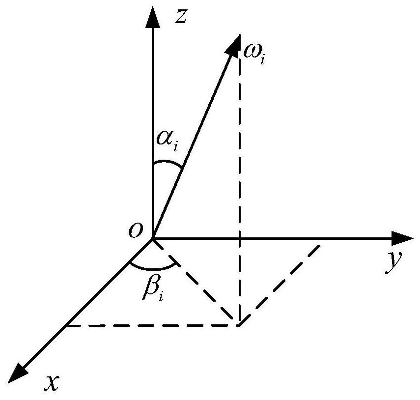
[0048] Specific embodiments of the present invention are as figure 1 As shown, the specific implementation steps are as follows:

[0049] (1) According to the characteristic that the constant value error of the redundant configuration IMU is formed by the linear combination of the constant value errors of its various sensors, a general redundant IMU constant value error model is constructed:

[0050]

[0051]

[0052] in, are the equivalent gyroscope constant errors of the IMUx, y, and z axes, respectively, IMUx, y, and z-axis equivalent accelerometer constant error, i is the serial number of the gyroscope or accelerometer, n is the total number of gyroscopes or accelerometers, ε i is the constant error of the i-th gyroscope, ▽ i is the constant error of the i-th accelerometer, k gxi 、k gyi 、k gzi are the weights of the i-th gyro constant value error in the equivalent gyro constant value error of the IMUx, y, and z axes, k...


PUM


Abstract

The invention relates to a redundant configuration inertial measurement unit biaxial rotation modulation method. A universal redundant inertial measurement unit constant error model is constructed byutilizing the characteristic that a redundant configuration inertial measurement unit constant error is formed by linearly combining sensor constant errors of the redundant configuration inertial measurement unit constant error, and constant error modulation is performed on the redundant inertial measurement unit through double-axis rotation to realize error compensation. On the basis, the influence of carrier angular motion on biaxial rotation modulation in actual navigation is considered, a biaxial rotation scheme based on an attitude angle is provided to realize error modulation under a navigation system, the carrier angular motion is effectively isolated, and the error modulation effect is improved. According to the invention, constant error modulation can be carried out on the redundant configuration inertial measurement unit, a good modulation effect can still be achieved under the condition that the carrier performs angular motion, and the navigation precision of the redundant configuration inertial measurement unit is significantly improved. The invention belongs to the technical field of inertial navigation, and the method can be applied to error compensation of the redundant configuration inertial measurement unit.

Description

technical field [0001] The invention relates to a dual-axis rotation modulation method of a redundantly configured inertial measurement unit, which is suitable for the occasion of error compensation of a redundantly configured inertial measurement unit. [0002] technical background [0003] Inertial navigation is the core technology for autonomous navigation of various vehicles, so the navigation accuracy and reliability of the inertial navigation system directly affect the navigation performance of the vehicle. The improvement of navigation accuracy and reliability of inertial navigation system can be achieved by improving the accuracy and reliability of inertial devices. It will be difficult to realize technically. Therefore, how to improve the navigation accuracy and reliability of the inertial navigation system has become a hot topic of research by various research institutions under the condition of certain accuracy and reliability of the inertial device. [0004] In t...

Claims


Application Information

Patent Timeline
Patent Type & Authority Applications(China)
IPC IPC(8): G01C21/16G01C25/00
CPCG01C21/16G01C25/005
Inventor 任元朱挺王丽芬翟雪瑞陈晓岑张健邹涛
Owner PLA PEOPLES LIBERATION ARMY OF CHINA STRATEGIC SUPPORT FORCE AEROSPACE ENG UNIV
Learn More