Self-adaptive optical system based on all-optical neural network

An adaptive optics and neural network technology, applied in the field of adaptive optics system, can solve the problems of unavoidable time-consuming link of analog-to-digital conversion, difficulty in realizing KHz level control bandwidth, etc., and achieve the effect of low power consumption

Active Publication Date: 2021-01-05
LASER FUSION RES CENT CHINA ACAD OF ENG PHYSICS
View PDF16 Cites 3 Cited by
  • Summary
  • Abstract
  • Description
  • Claims
  • Application Information

AI Technical Summary

Problems solved by technology

The deep learning neural network based on the digital information system can obtain the solution relationship between the received image and the control response through training, but it cannot avoid time-consuming links such as analog-to-digital conversion, data transmission, and calculation, so it is difficult to achieve KHz-level control bandwidth

Method used


Image

  • Self-adaptive optical system based on all-optical neural network
  • Self-adaptive optical system based on all-optical neural network
  • Self-adaptive optical system based on all-optical neural network

Examples


Embodiment 1

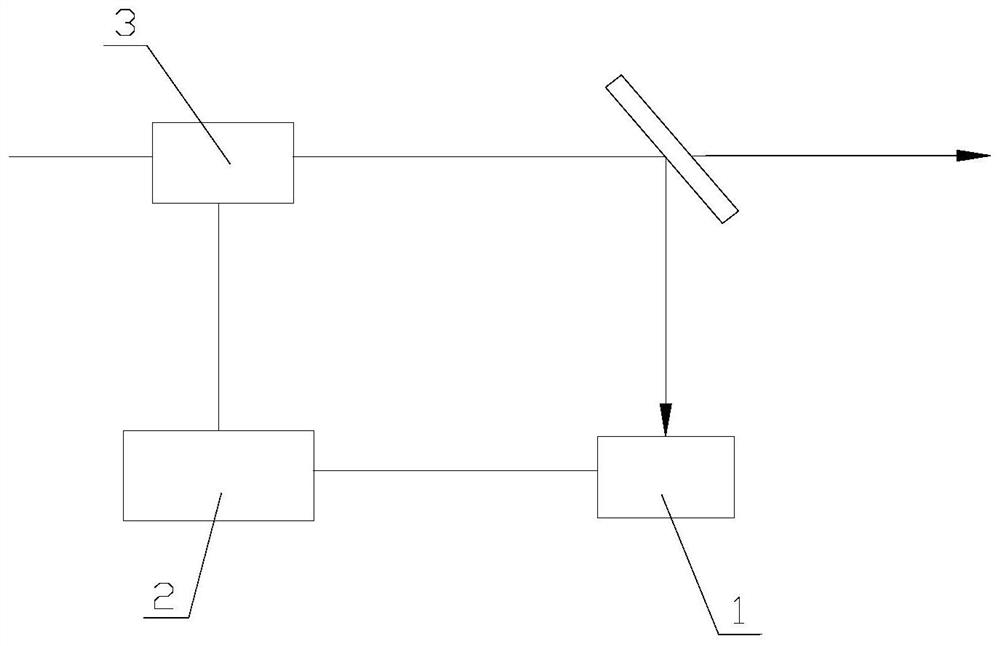
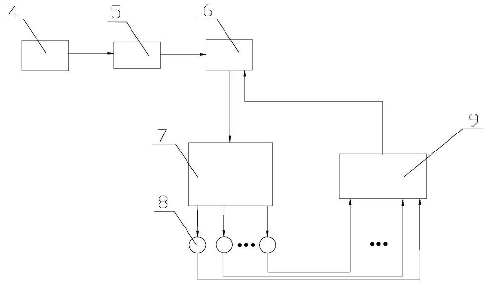
[0036] like figure 2 As shown, an adaptive optics system based on a plenoptic neural network includes a plenoptic neural network solver 7, a photovoltaic conversion array 8 and a high-voltage amplifier 9, wherein the target beam 4 passes through the optical channel including the boundary layer 5. Carrying the phase distortion information therein, the target beam 4 is reflected by the deformable mirror 6 to the all-optical neural network solver 7, and is resolved into the deformable mirror driving amount information (ie, the optical signal) defined by the beam intensity, and the target The light beam 4 is the light beam emitted or reflected by the target. The photovoltaic conversion array 8 is used to convert the information of the driving amount of the deformable mirror into a weak analog signal, that is, the photovoltaic conversion array 8 converts the optical signal into an electrical signal. At the same time, the weak analog signal is passed through the high voltage The am...

Embodiment 2

[0043] like image 3 As shown, the same parts of this embodiment and Embodiment 1 will not be repeated, and the difference is:

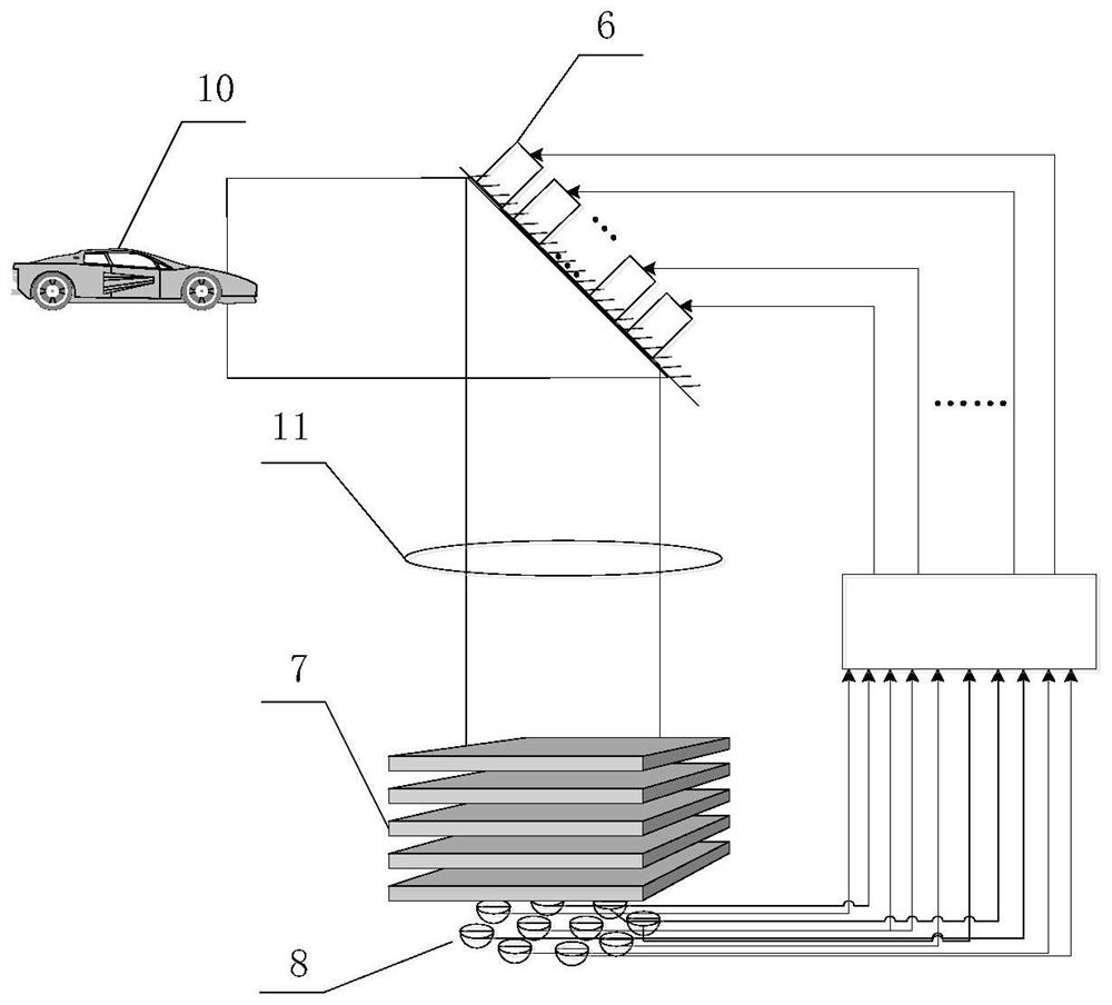
[0044] The target beam is the beam emitted or reflected by the target 10 .

[0045] Deformable mirror 6 has 19 actuating units, and its actuating units are distributed as Figure 4 shown. During the training data acquisition process, 50,000 wavefront distortion distributions are randomly generated.

[0046] The all-optical neural network solver 7 is made of 5 optical diffraction plates, and the cross-section of the optical diffraction plates is a square, its side length is 1 millimeter, and the distance between adjacent optical diffraction plates is 100 microns. face like Figure 5 As shown, among them, image 3 The five optical diffraction plates shown are represented by pp1, pp2, pp3, pp4, and pp5 sequentially from top to bottom.

[0047] The photovoltaic conversion array 8 includes 19 conversion units, the arrangement of which is the same as...


PUM


Abstract

The invention relates to a self-adaptive optical system based on an all-optical neural network, which belongs to the technical field of self-adaptive optical systems and comprises an all-optical neural network solver, a photovoltaic conversion array and a high-voltage amplifier. According to the invention, the all-optical neural network solver formed by optical diffraction plates is used for solution and modulation of a target light beam, and the target light beam is converted to an optical signals. The self-adaptive optical system is used for replacing a wavefront sensing device, a signal resolving device, a digital-to-analog conversion device and the like in a traditional self-adaptive optical system, the response bandwidth can reach the KHz magnitude, the high-bandwidth wavefront control requirement under a non-cooperative target scene can be met, meanwhile, a traditional circuit is replaced by the optical path, and the cost is reduced. Operation from a target light beam to a deformable mirror driving electric signal is achieved with extremely low power consumption and extremely high response speed, the effect of real-time wavefront correction is achieved, and the self-adaptiveoptical system can be applied to military and other scenes with high response bandwidth requirements for light beam wavefront correction.

Description

technical field [0001] The invention belongs to the technical field of adaptive optical systems, and in particular relates to an adaptive optical system based on an all-optical neural network. Background technique [0002] In view of the sensitivity of the laser to the phase of the transmission channel, the phase disturbance caused by atmospheric turbulence and other effects will cause the disturbance of the laser beam wave surface, seriously reducing the focusing performance of the laser beam, thus limiting the ability of the laser as a means of long-distance combat. In order to solve the problem of wavefront disturbance in atmospheric turbulence, adaptive optics (AO) technology, which can correct beam wavefront, came into being. A typical adaptive optics wavefront control system is mainly composed of three basic parts such as wavefront sensor, control processor, and wavefront corrector to form a basic closed-loop control system, such as figure 1 shown. The function of th...

Claims


Application Information

Patent Timeline
Patent Type & Authority Applications(China)
IPC IPC(8): G02B26/06G06N3/067G06N3/08
CPCG02B26/06G06N3/067G06N3/08
Inventor 胡东霞耿远超黄晚晴王德恩刘兰琴王文义张颖孙喜博
Owner LASER FUSION RES CENT CHINA ACAD OF ENG PHYSICS
Why Eureka
Try Eureka