Inductor and forming method thereof

A technology of inductance and magnetic core, applied in the field of inductance, can solve the problem of high noise, achieve the effect of low noise, reduce DCR, and improve current resistance characteristics

Pending Publication Date: 2021-01-05
海宁科优力电子科技有限公司
View PDF0 Cites 0 Cited by
  • Summary
  • Abstract
  • Description
  • Claims
  • Application Information

AI Technical Summary

Problems solved by technology

[0002] With the rapid development of the electronics industry, the performance requirements of products are getting higher and higher. With the continuous upgrading of high-end electronic equipment and technological innovation, it directly drives the further development of electronic components. In the existing technology, inductors are the core electronic components. , the coil usually needs to be die-cast with the magnetic material, so that the terminal is determined on the side of the magnetic core, and the terminal usually protrudes from the side of the magnetic core, but its disadvantage is that it is noisy below 20KHZ

Method used


Image

  • Inductor and forming method thereof
  • Inductor and forming method thereof

Examples


Embodiment

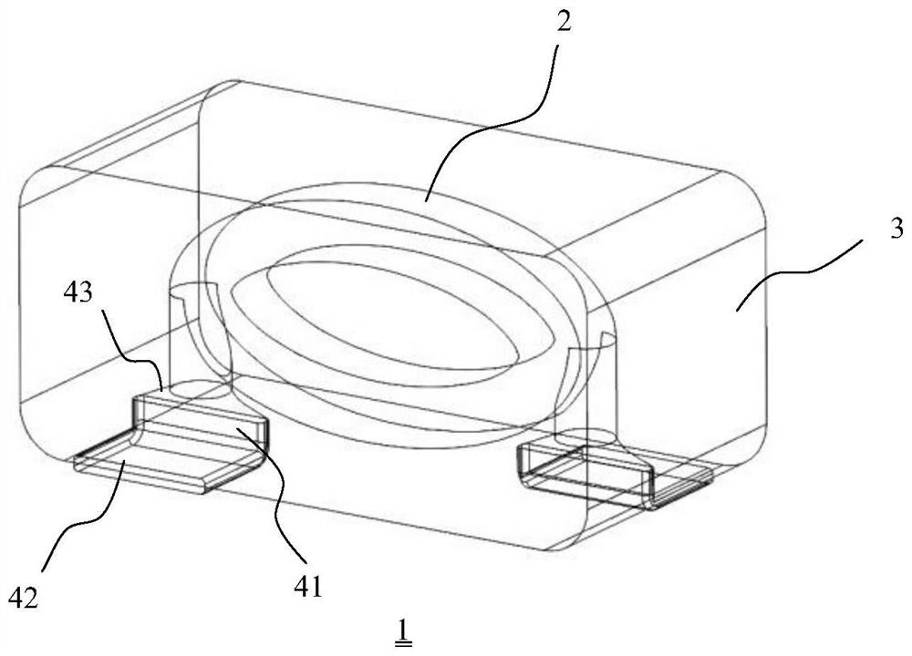
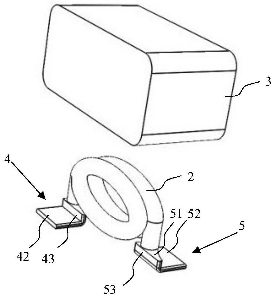
[0025] The invention discloses an inductor 1, which can be applied to high-end graphics card equipment to meet the requirements of the market for high current resistance, low loss and low noise. Specifically, figure 1 A schematic diagram of the inductor 1 of the present invention is disclosed, including a coil 2 and a magnetic core 3, the magnetic core 3 is a rectangular parallelepiped structure, the coil 2 is accommodated inside the magnetic core 3, and the magnetic core 3 with a rectangular parallelepiped structure can be used on a PCB More inductors 1 can be accommodated in a unit area, increasing power density.

[0026] The magnetic core 3 is made of magnetic materials, usually made of amorphous and carbonyl powders in a certain ratio and optimally configured.

[0027] The main part of the coil 2 is wound into an oval structure, which has a first end and a second end, and the first end of the coil 2 and the second end of the coil 2 are respectively connected to terminals. ...


PUM


Abstract

The invention discloses an inductor which comprises a coil and a magnetic core, wherein the coil is accommodated in the magnetic core, one end of the coil is connected with a first terminal, and the other end of the first terminal extends to the outside of the magnetic core and is bent; the other end of the coil is connected with a second terminal, and the other end of the second terminal extendsto the outside of the magnetic core and is bent. An inductor forming method comprises the following steps that S1, a coil and a terminal are welded and put into a mold cavity of a mold, the mold is filled with a powdery magnetic material, and a product consistent with the mold cavity in shape is formed after pressurization; S2, the product is heated and cured; S3, the terminal of the cured productis bent. By means of the technical scheme, the product has the advantage of being low in noise.

Description

technical field [0001] The invention relates to the technical field of inductors, in particular to an inductor and a processing and forming method for the inductor. Background technique [0002] With the rapid development of the electronics industry, the performance requirements of products are getting higher and higher. With the continuous upgrading of high-end electronic equipment and technological innovation, it directly drives the further development of electronic components. In the existing technology, inductors are the core electronic components. , the coil usually needs to be die-cast with the magnetic material, so that the terminal is determined on the side of the magnetic core, and the terminal usually protrudes from the side of the magnetic core, but its disadvantage is that it is noisy below 20KHZ. Contents of the invention [0003] In order to solve the above-mentioned technical problems, the inventor has found through long-term research that when faced with th...

Claims


Application Information

Patent Timeline
Patent Type & Authority Applications(China)
IPC IPC(8): H01F27/29H01F27/04H01F27/33H01F17/04H01F41/00
CPCH01F17/04H01F27/04H01F27/29H01F27/33H01F41/005H01F2017/048
Inventor 茆世安
Owner 海宁科优力电子科技有限公司
Why Eureka
Try Eureka