
Laminating and heat-sealing clamping mechanism for lead-acid storage battery

A technology of lead-acid battery and clamping mechanism, which is applied in the direction of lead-acid battery, lead-acid battery construction, climate sustainability, etc. It can solve the problems of easy leakage of liquid, decline of heat sealing effect, hidden safety hazards, etc., and achieve convenient fixed support Board height, easy to disassemble, not easy to fall off

Active Publication Date: 2021-01-05
ANHUI NARADA RENEWABLE RESOURCE TECH CO LTD
View PDF8 Cites 1 Cited by
  • Summary
  • Abstract
  • Description
  • Claims
  • Application Information

AI Technical Summary

Problems solved by technology

[0005] Aiming at the deficiencies of the prior art, the present invention provides a film-coated heat-sealing clamping mechanism for a lead-acid battery, which has the advantages of tightening the battery and dissipating heat, and solves the need to use clamps when heat-sealing the battery film. The battery is clamped by the holding mechanism. When the top of the existing lead-acid battery needs to be covered and heat-sealed, it is generally processed manually. In this way, the top cover of the battery is easily skewed due to force, which will cause a decline in the heat-sealing effect. , so that the yield rate is greatly reduced, and the internal liquid is easy to leak, causing safety hazards

Method used


Image

  • Laminating and heat-sealing clamping mechanism for lead-acid storage battery
  • Laminating and heat-sealing clamping mechanism for lead-acid storage battery
  • Laminating and heat-sealing clamping mechanism for lead-acid storage battery

Examples


Embodiment Construction

[0029] The following will clearly and completely describe the technical solutions in the embodiments of the present invention with reference to the accompanying drawings in the embodiments of the present invention. Obviously, the described embodiments are only some, not all, embodiments of the present invention. Based on the embodiments of the present invention, all other embodiments obtained by persons of ordinary skill in the art without making creative efforts belong to the protection scope of the present invention.

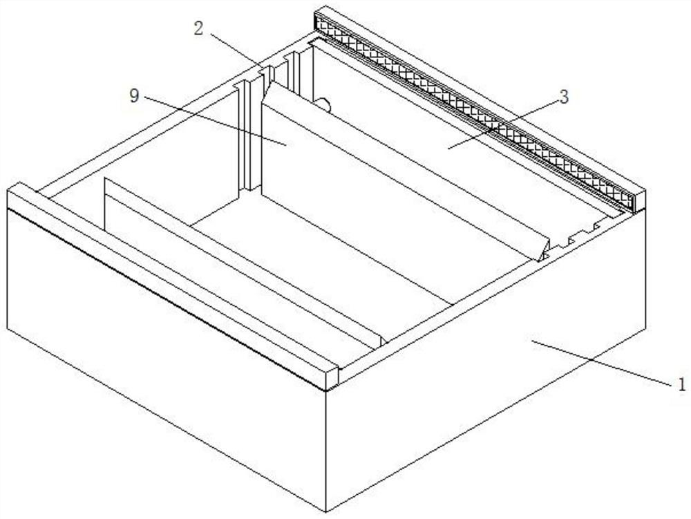
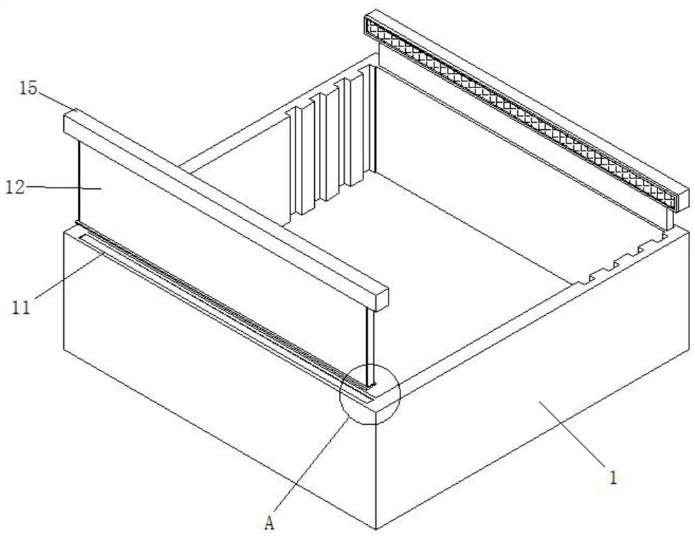
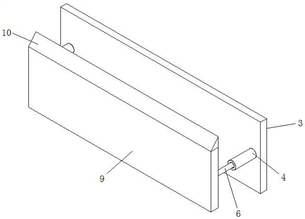
[0030] see Figure 1-7 , a film-coated heat-seal clamping mechanism for a lead-acid battery, comprising a housing 1, the housing 1 is a rectangular hollow structure, the top surface of the housing 1 is open, and both sides of the housing 1 are provided with internal Slot 2, the inner slot 2 is a rectangular slot, and the internal activity of the inner slot 2 is clamped with a block 3, the block 3 is a rectangular structure, and both sides of one side of the bl...


PUM


Abstract

The invention relates to the technical field of lead-acid storage batteries, and discloses a lead-acid storage battery laminating heat-sealing clamping mechanism which comprises a shell, the shell isof a rectangular hollow structure, the top surface of the shell is open, inner grooves are formed in the two sides of the interior of the shell, the inner grooves are rectangular grooves, clamping blocks are movably clamped in the inner grooves, and the clamping blocks are of rectangular structures. A plurality of inner grooves are formed in a shell, a plurality of clamping blocks are arranged inthe inner grooves, the positions of the clamping blocks can be adjusted according to actual conditions, four outer columns are arranged on one side of each clamping block, every two outer columns forma group, one group of outer columns are fixedly mounted on one side of each clamping block, and the other group of outer columns are fixedly mounted on one side of the interior of the shell; whereinan inner column is arranged in the outer column, extrusion blocks are arranged at one end of the inner column, a battery needing to be subjected to film covering and heat sealing is placed between thetwo extrusion blocks, a spring is arranged at one end of the inner column, and the two extrusion blocks are close to each other under the force of the spring, so that the clamping and fixing effectsare achieved.

Description

technical field [0001] The invention relates to the technical field of lead-acid batteries, in particular to a film-covered heat-sealing clamping mechanism for lead-acid batteries. Background technique [0002] All batteries that use acidic aqueous solution as electrolyte are collectively called acid batteries, the most typical of which is lead-acid batteries. The main advantages of acid storage batteries are high working voltage, wide operating temperature, good high and low rate discharge performance, abundant raw material sources, and low price. The disadvantage is that the energy density is low, which makes it larger in size and weight. For lead-acid batteries, the positive electrode is lead dioxide, the negative electrode is spongy lead, the electrolyte is sulfuric acid aqueous solution, and the separator (diaphragm) is used according to different types of lead-acid batteries. Microporous rubber separators, microporous plastic separators or other materials, and the bat...

Claims


Application Information

Patent Timeline
IPC IPC(8): H01M10/12
CPCH01M10/12Y02E60/10Y02P70/50
Inventor 王武钧朱保义胡磊任永刚
Owner ANHUI NARADA RENEWABLE RESOURCE TECH CO LTD
Learn More