Supercharge Your Innovation With Domain-Expert AI Agents!

Antenna array assembly for direction finding and device for direction finding

A technology of antenna arrays and components, which is applied to antenna arrays, antenna arrays, antennas, etc. that are powered separately, and can solve the problems of large space occupied by terminals, high cost of glue stick antennas, and reduced radiation field strength.

Pending Publication Date: 2021-01-05
TELINK SEMICON SHANGHAI
View PDF0 Cites 0 Cited by
  • Summary
  • Abstract
  • Description
  • Claims
  • Application Information

AI Technical Summary

Problems solved by technology

like figure 1 As shown, multiple glue stick antennas are vertically installed on the RF PCB through the antenna interface. Although the radiation field intensity distribution of the glue stick antenna on the horizontal plane (relative to the RF PCB) is relatively uniform, the direction from the horizontal direction to the vertical direction (RF PCB) front), the radiation field strength tends to decrease significantly, which is not conducive to the uniformity of the direction-finding accuracy in all directions of the above-mentioned direction-finding method, and because the size of the glue stick antenna itself is relatively large, especially long, it will take up space in the terminal Larger, and the cost of the glue stick antenna itself is higher
[0005] In another antenna array with PIFA antenna as the array element, the PIFA antenna adopts the RF PCB board-mounted antenna structure, so it occupies less space in the terminal and has lower cost, but its radiation field strength distribution also has the problem of not being ideal

Method used


Image

  • Antenna array assembly for direction finding and device for direction finding
  • Antenna array assembly for direction finding and device for direction finding
  • Antenna array assembly for direction finding and device for direction finding

Examples


Embodiment Construction

[0030] Various embodiments will be described in detail with reference to the accompanying drawings. Wherever possible, the same reference numbers will be used throughout the drawings to refer to the same or like parts. References made to specific examples and implementations are for purposes of illustration, and are not intended to limit the scope of the application or the claims.

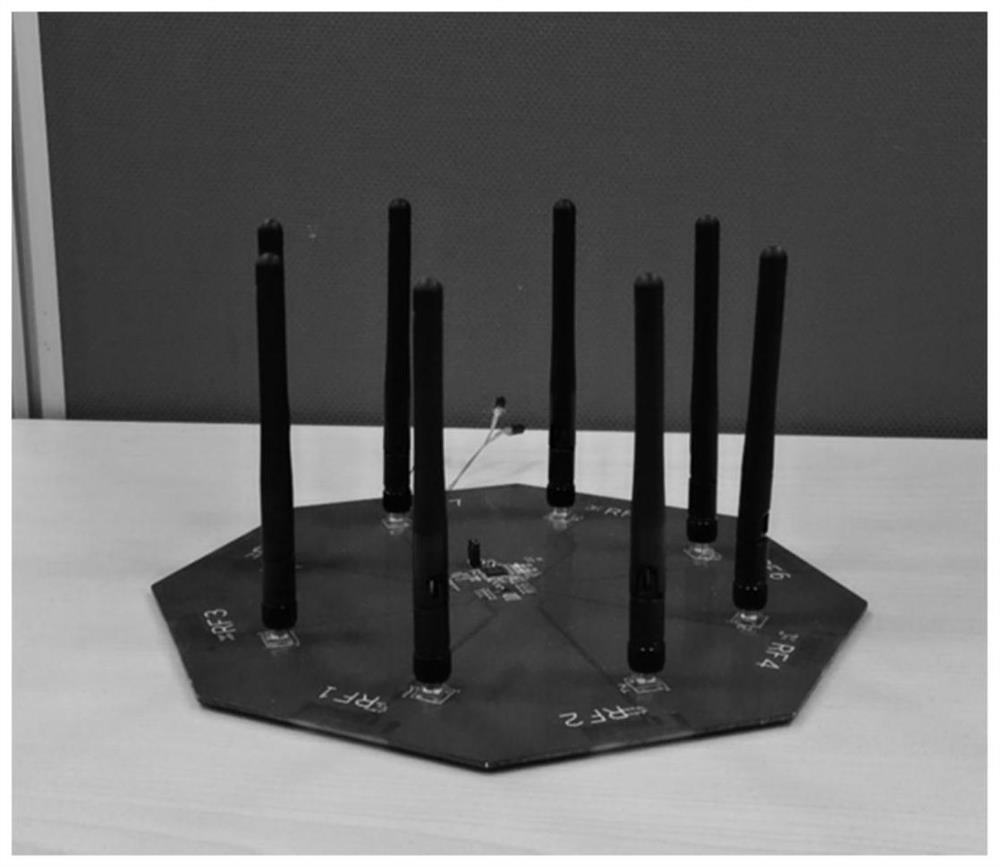
[0031] One aspect of the present application provides an antenna array assembly for direction finding, the antenna array assembly includes a radio frequency printed circuit board (RF PCB) and an antenna array connected to the RF PCB, wherein the antenna array uses a patch antenna as an array element , and use RF PCB as the dielectric substrate.

[0032] The following combination Figure 3 to Figure 9 An antenna array assembly for direction finding according to an embodiment of the present application will be described in detail.

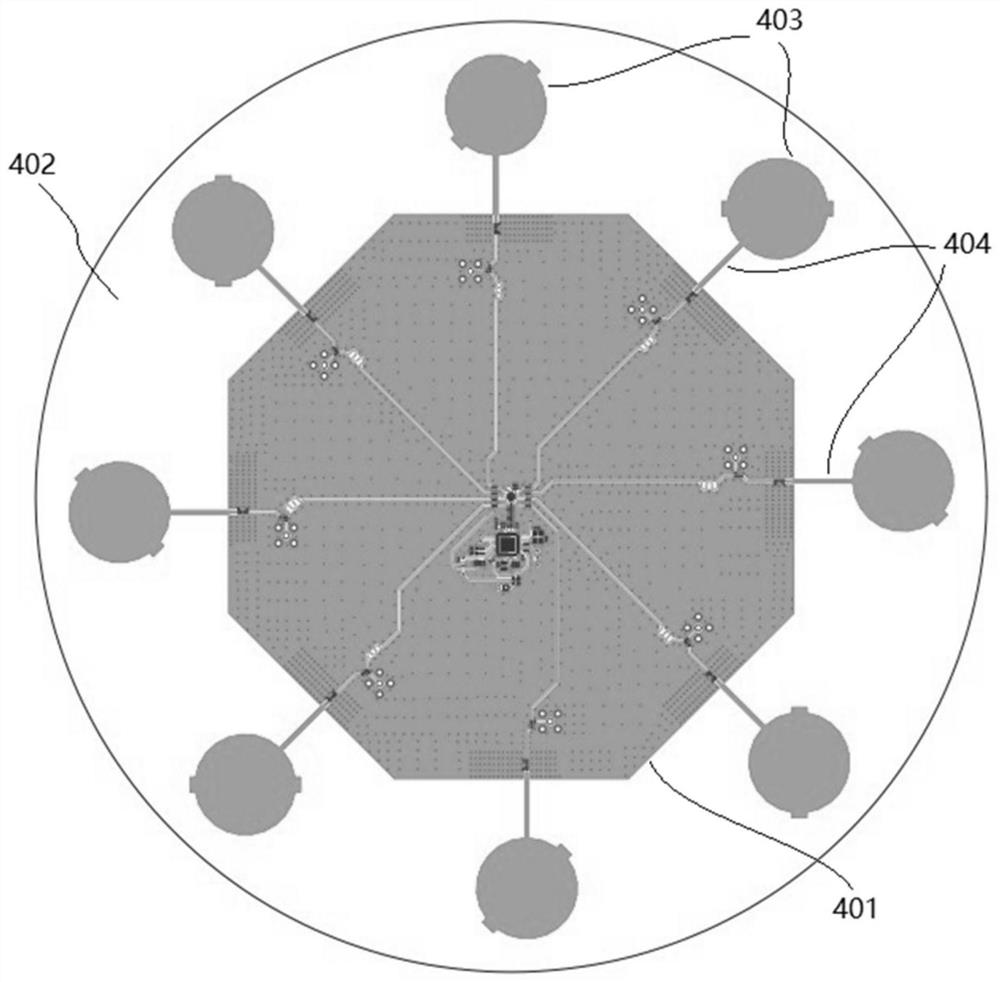
[0033] image 3 It is a schematic plan view of an antenna array ...


PUM


Abstract

The invention discloses an antenna array assembly for direction finding, wherein the antenna array assembly comprises a radio frequency printed circuit board and an antenna array connected with the radio frequency printed circuit board, and the antenna array takes a patch antenna as an array element and takes the radio frequency printed circuit board as a dielectric substrate.

Description

technical field [0001] The embodiments of the present application relate to the field of wireless communication technologies, and in particular, to an antenna array assembly for direction finding and a device for direction finding. Background technique [0002] In the field of radio direction finding, direction finding technology has been continuously improved, especially after the introduction of methods involving signal phase comparison, radio direction finding has made significant progress and has been widely used. For example, the direction finding method based on the angle of arrival (AOA) and the direction finding method based on the angle of departure (AOD) are applied in the indoor positioning system, wherein, in the direction finding method based on the AOA, the receiving end including the antenna array receives The wireless signal from the transmitting end, and calculate the AOA of the wireless signal based on the phase difference between the wireless signals recei...

Claims


Application Information

Patent Timeline
Patent Type & Authority Applications(China)
IPC IPC(8): H01Q1/38H01Q1/50H01Q21/06
CPCH01Q1/38H01Q1/50H01Q21/065
Inventor 黄海力梁文豪
Owner TELINK SEMICON SHANGHAI
Features
  • R&D
  • Intellectual Property
  • Life Sciences
  • Materials
  • Tech Scout
  • Unparalleled Data Quality
  • Higher Quality Content
  • 60% Fewer Hallucinations
Learn More