Cable support with looseness warning function

A cable support and function technology, which is applied to the cable support field with a loose warning function, can solve the problems of no warning mechanism, the fixing bolts are easy to loosen and fall off, and the normal use of the cable trench is affected, and the effect of improving work efficiency and avoiding damage can be achieved.

Active Publication Date: 2021-01-05
广州中科工程建设有限公司
View PDF10 Cites 2 Cited by
  • Summary
  • Abstract
  • Description
  • Claims
  • Application Information

AI Technical Summary

Problems solved by technology

[0005] The purpose of the present invention is to solve the shortcomings existing in the prior art that the cable bracket in the traditional cable trench is easily deformed under pressure, the fixing bolts are easy to loosen and fall off, and there is no warning mechanism, which affects the normal use of the cable trench. A kind of cable bracket with loose warning function

Method used


Image

  • Cable support with looseness warning function
  • Cable support with looseness warning function
  • Cable support with looseness warning function

Examples


Embodiment 1

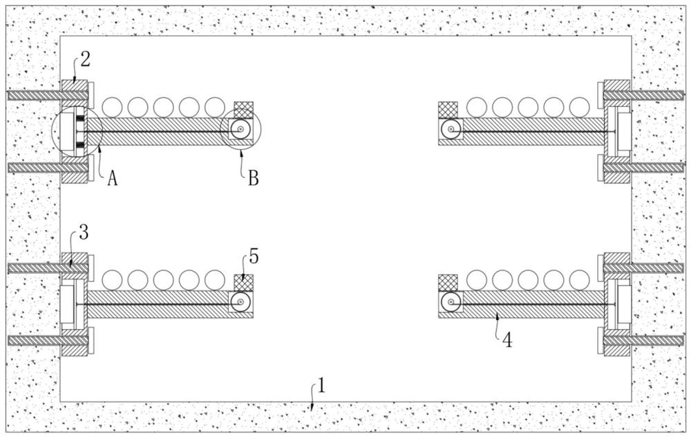
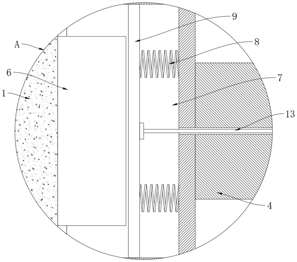
[0022] refer to Figure 1-3 , a cable bracket with a loosening warning function, comprising a channel 1, a plurality of vertical plates 2 are symmetrically installed on the inner wall of the channel 1 through fixing bolts 3, and each vertical plate 2 is horizontally and fixedly connected with a wall for placing cables. The board 4 is placed, and the side of each vertical board 2 close to the inner wall of the channel 1 is provided with a mounting groove 7, and each mounting groove 7 is vertically elastically connected with a movable plate 9 through a return spring 8, and each movable plate 9 All are slidingly connected to the groove wall of the corresponding installation groove 7, and the inner wall of the channel 1 is evenly and fixedly connected with a plurality of top blocks 6 corresponding to the installation groove 7;

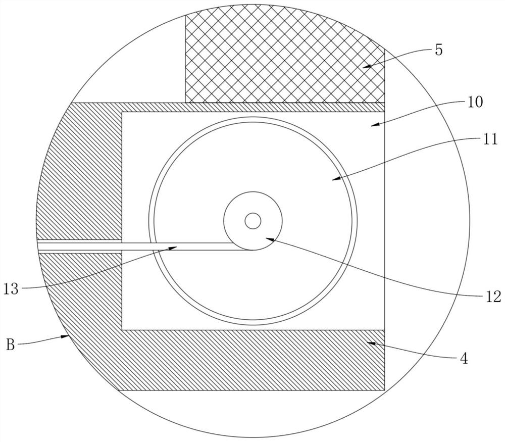
[0023] The end of each placement plate 4 away from the corresponding vertical plate 2 is provided with a storage slot 10, and each storage slot 10 is equi...

Embodiment 2

[0027] refer to Figure 4 The difference between this embodiment and Embodiment 1 is that each placement plate 4 is provided with a placement slot 14 corresponding to the storage slot 10, and each rotating shaft extends into the corresponding placement slot 14 and is interference-fitted with a permanent Magnetic sleeve 15, each placement slot 14 is provided with an induction coil 16 that cooperates with the permanent magnetic sleeve 15, and each induction coil 16 is coupled with an external signal receiver through a wire, and the external signal receiver includes a single-chip microcomputer to analyze the signal Positioning, and this part is the prior art and will not be described here.

[0028] This embodiment can illustrate its functional principle through the following operation mode: under the influence of the external environment, when the cable bracket suddenly falls off, the corresponding movable plate 9 slides quickly in the installation groove 7 under the elastic forc...


PUM


Abstract

The invention discloses a cable support with a looseness warning function, which comprises a channel, a plurality of vertical plates are symmetrically arranged on the inner wall of the channel throughfixing bolts, each vertical plate is horizontally and fixedly connected with a placement plate for placing a cable, and a mounting groove is formed in one side, close to the inner wall of the channel, of each vertical plate; a movable plate is elastically connected into each mounting groove through a reset spring, and a plurality of ejector blocks corresponding to the mounting grooves are evenlyand fixedly connected to the inner wall of the channel. According to the invention, when the cable support is deformed or the bolt is loosened, the indication roller can be driven to rotate through the cooperation of the reset spring, the movable plate and the pull wire, so that the position of the indication mark on the indication roller is changed, and an inspector can directly judge whether thesupport is loosened or not through the indication mark on the indication roller; therefore, timely processing can be realized, one-by-one inspection is not needed, and the working efficiency of inspection personnel is further improved.

Description

technical field [0001] The invention relates to the technical field of cable supports, in particular to a cable support with a loosening warning function. Background technique [0002] The cable trench can reduce the occupation of the above-ground space of the cable duct, and can also effectively reduce the impact of people's daily life on the cable. Therefore, many cities use cable trenches to lay cables, and the cables in the cable trench play a role in supporting the cables. For convenience For cable placement and inspection, cable brackets are often installed on one or both sides of the cable trench, and a certain width channel is left between the brackets on both sides or between the bracket and the side wall of the cable trench (one-sided bracket). [0003] In actual use, according to the principle of leverage, the end of the cable bracket far away from the wall of the cable trench is subject to a large force. After a long time of use, the cable bracket is likely to be...

Claims


Application Information

Patent Timeline
IPC IPC(8): H02G3/04H02G9/06G08B21/18G09F7/00
CPCG08B21/18G09F7/00H02G3/0406H02G3/0456H02G9/06
Inventor 张王双
Owner 广州中科工程建设有限公司
Why Eureka
Try Eureka