
Camera system control method and device and camera device

A control method and technology of a control device, which are applied to components of TV systems, components of color TVs, TVs, etc., can solve problems such as pixel crosstalk, information overlap, and image ghosting.

Active Publication Date: 2021-01-05
WEIHAI HUALING OPTO ELECTRONICS CO LTD
View PDF6 Cites 0 Cited by
  • Summary
  • Abstract
  • Description
  • Claims
  • Application Information

AI Technical Summary

Problems solved by technology

[0005] The main purpose of this application is to provide a control method, a control device and a camera device for a camera system, so as to solve the problems in the prior art that the information on the manuscript is overlapped, resulting in crosstalk between pixels and causing image ghosting

Method used


Image

  • Camera system control method and device and camera device
  • Camera system control method and device and camera device
  • Camera system control method and device and camera device

Examples


Embodiment 1

[0082] Such as Figure 5 As shown in the camera device, the camera device includes a camera system and a control system. The camera system is provided with a supporting frame 206, and a plurality of lenses 200 are arranged in the frame 206. The number of the above-mentioned lenses 200 can be four, and the above-mentioned A circuit board 203 is provided below the lens 200, and a photoelectric conversion chip 201 is respectively provided directly below the four above-mentioned lenses 200 on the circuit board 203. The chips 201 correspond one to one, and a plurality of light sources 202 are uniformly arranged above the lens 200 . The back side of circuit board is provided with first socket 207, and above-mentioned control system comprises circuit board 203, FPGA chip 204 and light source control chip 205, and above-mentioned circuit board 203 is provided with second socket 208 and the 3rd socket 209, and above-mentioned FPGA chip 204 comprises The camera control module 300 , the...

Embodiment 2

[0088] Figure 7 A simple schematic diagram for controlling the above-mentioned light source 202 using the above-mentioned MOS tube 303, Figure 8 After adding the Vdrive voltage to the G and S terminals of the above-mentioned MOS transistor 303, the voltage and the drain current I D change curve. As can be seen from the figure, from the addition of V drive voltage, to the I D When the voltage reaches the maximum value, there is a time period of Δt20. Although the time is relatively short, a very short light source lighting time is required, which creates a contradiction: if the above-mentioned light source is triggered in a very short time after the shutter of the camera is opened 202 is on and off, wherein, the above-mentioned light source 202 can be an LED, and it is very likely that the brightness of the above-mentioned light source 202 will start to go out before it reaches a stable level, such as Figure 9 As shown, or the time for stable brightness is relatively sho...


PUM


Abstract

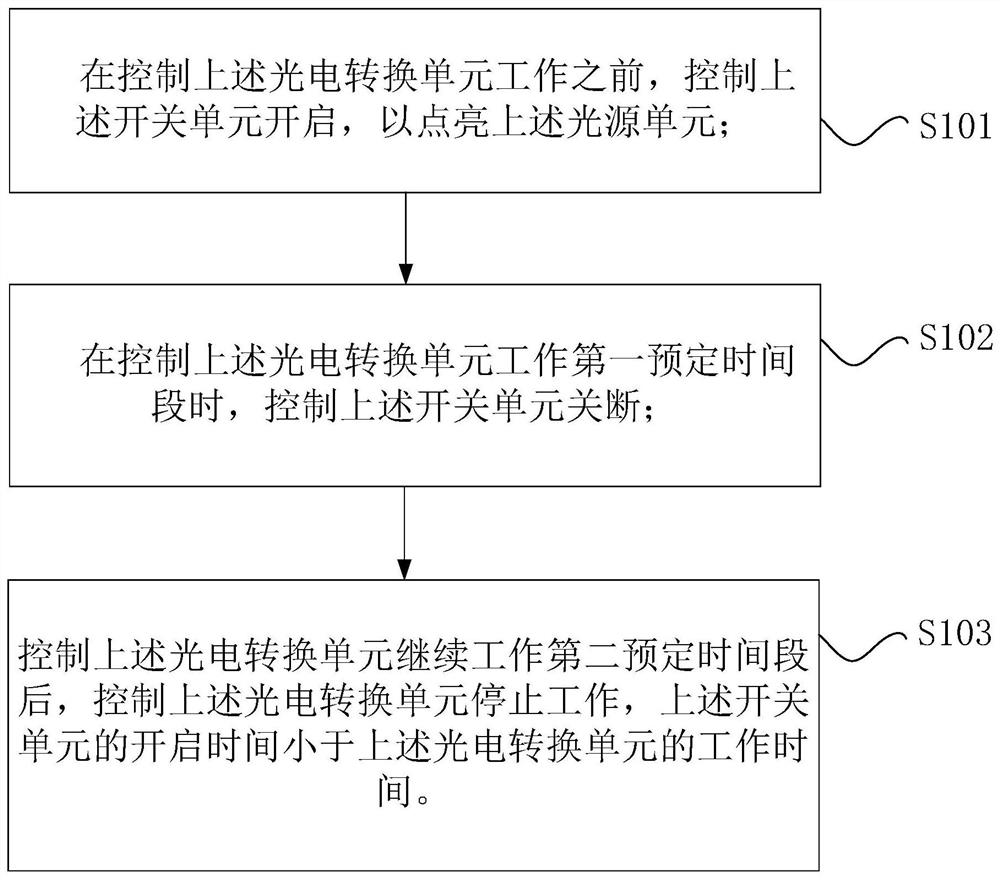
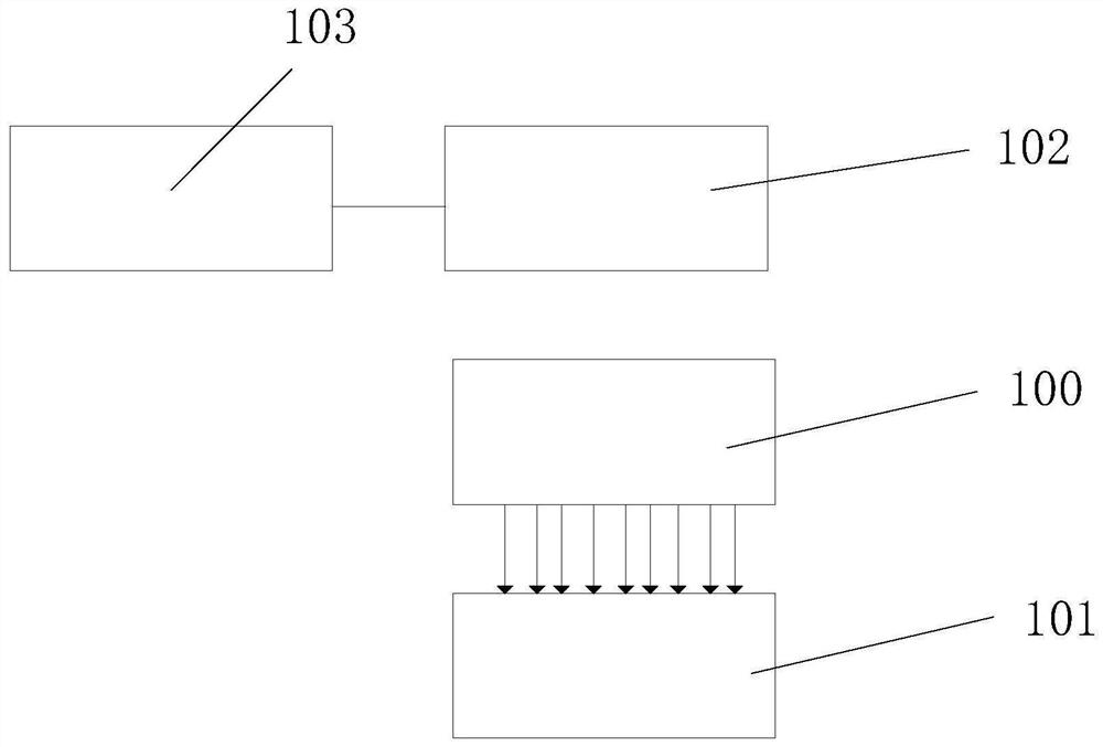
The invention provides a camera system control method and device and a camera device. A camera system comprises a lens unit, a photoelectric conversion unit, a light source unit and a switch unit, wherein the photoelectric conversion unit is located on one side of the lens unit; the light source unit is located on the side, away from the photoelectric conversion unit, of the lens unit; the emergent light of the lens unit enters the photoelectric conversion unit; and the switch unit is electrically connected with the light source unit and used for controlling the light source unit to work. Thecontrol method comprises the steps that before the photoelectric conversion unit is controlled to work, the switch unit is controlled to be turned on to turn on the light source unit; when the photoelectric conversion unit is controlled to work for a first preset time period, the switch unit is controlled to be turned off; after the photoelectric conversion unit is controlled to continue to work for a second preset time period, the photoelectric conversion unit is controlled to stop working, wherein the starting time of the switch unit is shorter than the working time of the photoelectric conversion unit. According to the method, the problem that information on a manuscript is overlapped along with movement of the manuscript in the prior art is solved.

Description

technical field [0001] The present application relates to the field of cameras, in particular, to a control method, a control device and a camera device of a camera system. Background technique [0002] Existing area scan cameras, whether they are CCD cameras or CMOS cameras, whether they are rolling shutter cameras or global exposure cameras, have the function of controlling the exposure time and do not need to control the light source. [0003] In the field of high-speed scanning and high-resolution detection, the length and width of a unit pixel are very small. When scanning, the original moves very fast, and the exposure time of the camera itself is relatively long. Therefore, in the exposure time of one frame, as the original moves, the information on the original will inevitably overlap, resulting in crosstalk between pixels and causing image ghosting. [0004] The above information disclosed in the Background section is only to enhance the understanding of the backgr...

Claims


Application Information

Patent Timeline
IPC IPC(8): H04N5/225H04N5/235
CPCH04N23/55H04N23/54H04N23/73
Inventor 姜利韩晓伟
Owner WEIHAI HUALING OPTO ELECTRONICS CO LTD
Learn More