Valve prosthesis with variable positioning piece and conveying system thereof

A technology of valve prosthesis and positioning parts, which is applied in the field of medical devices, can solve problems such as inability to resist the impact of blood and inaccurate release positioning, and achieve the effects of increasing connection stability, improving accuracy, and reducing trauma

Pending Publication Date: 2021-09-28
NINGBO JENSCARE BIOTECHNOLOGY CO LTD
View PDF1 Cites 1 Cited by
  • Summary
  • Abstract
  • Description
  • Claims
  • Application Information

AI Technical Summary

Problems solved by technology

The technology of the present invention has the characteristics of accurate positioning, stable clamping, firm clamping, and reduced paravalvular leakage, and solves the problems in the prior art that the positioning part of the prosthesis cannot resist the impact of blood and the release positioning is not accurate.

Method used


Image

  • Valve prosthesis with variable positioning piece and conveying system thereof
  • Valve prosthesis with variable positioning piece and conveying system thereof
  • Valve prosthesis with variable positioning piece and conveying system thereof

Examples


specific Embodiment 1

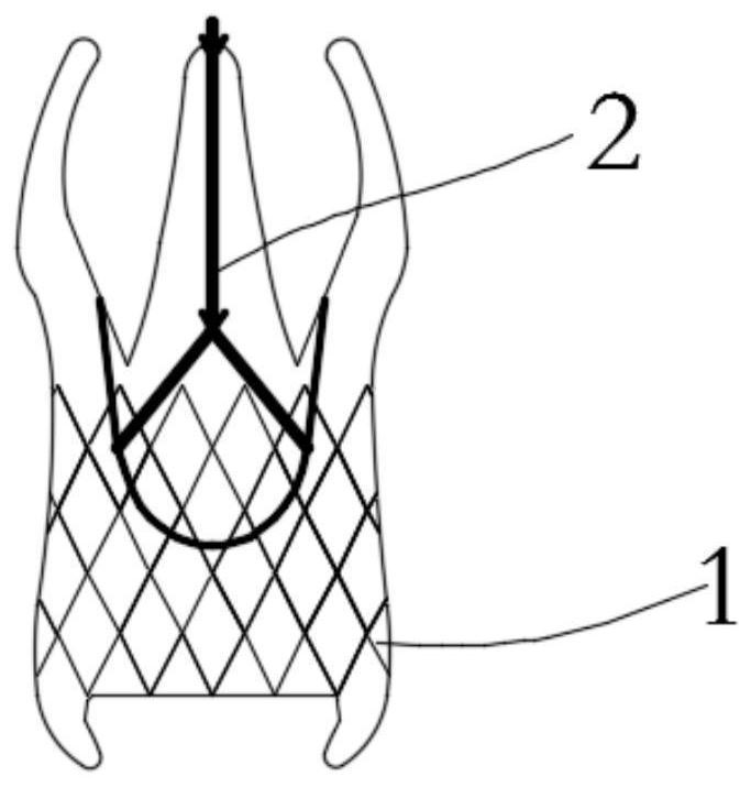
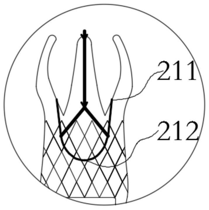
[0050] When the heart valve prosthesis is used to treat aortic valve disease, such as Figures 1a-1d As shown, it includes a stent body 1, a positioning member 2 and an artificial valve 3, the artificial valve 3 is connected to the stent body 1, the positioning member 2 includes a positioning arm 21 and a control member 22, and the control member 22 One end of the locating arm 21 is matched and connected to the positioning arm 21. The locating arm 21 has a fixed end 211 and a free end 212. The fixed end 211 is fixedly connected to the support body 1. When the control member 22 pulls the positioning arm 21 , the free end 212 of the positioning arm 21 moves along the height direction of the support body 1, and when the positioning member 2 is in the released state, the positioning arm 21 returns to a preset shape (such as Figure 2a shown); when the positioning member 2 is in the restricted state, the free end 212 of the positioning arm 21 does not overlap with the stent body 1,...

specific Embodiment 2

[0067] In order to better illustrate the working principle of the present invention, the release process of the artificial valve 3 prosthesis of the present invention will be described step by step below:

[0068] Such as Figure 7 As shown, when the heart valve prosthesis is used to treat aortic valve disease, as shown in the figure, it includes a stent body 1, a positioning member 2 and an artificial valve 3, and the artificial valve 3 is connected to the stent body 1, the positioning member 2 includes a positioning arm 21 and a control member 22, one end of the control member 22 is connected to the positioning arm 21, the positioning arm 21 has a fixed end 211 and a free end 212, the The fixed end 211 is fixedly connected with the support body 1. When the control member 22 pulls the positioning arm 21, the free end 212 of the positioning arm 21 moves along the height direction of the support body 1. When the positioning member 2 is released state, the positioning arm 21 re...


PUM


Abstract

The invention belongs to the field of medical instruments, and particularly relates to a valve prosthesis with a variable positioning piece and a conveying system thereof. The valve prosthesis comprises a support body, the positioning piece and an artificial valve, the artificial valve is connected to the support body, the positioning piece comprises a positioning arm and a control piece, one end of the control piece is connected to the positioning arm in a matched mode, the positioning arm is provided with a fixed end and a free end, the fixed end is fixedly connected with the support body, when the positioning piece is in a limiting state, the control piece axially stretches the positioning arm to enable the positioning arm to deform in the axial direction, and when the positioning piece is in a releasing state, the positioning arm axially recovers to be in a preset shape. The positioning piece is provided with the fixed end and the free end, the control piece can be used for axially pulling the positioning arm during loading, so that the positioning arm deforms, the positioning piece and the support body cannot be overlapped during loading, the pipe diameter of a loading sheathing canal of the conveying system is reduced, and trauma to a patient is greatly reduced.

Description

Technical field: [0001] The invention belongs to the field of medical devices, and in particular relates to a valve prosthesis with variable positioning parts and a delivery system thereof. Background technique: [0002] Aortic stenosis is mainly caused by sequelae of rheumatic fever, congenital aortic valve structural abnormalities, or senile aortic valve calcification. Patients are asymptomatic during the compensation period, but most patients with severe aortic valve stenosis have symptoms of fatigue, dyspnea (exertional or paroxysmal), angina pectoris, dizziness or syncope, and even sudden death. [0003] Aortic valve regurgitation means that the aortic valve opens when the ventricle contracts, the blood flow in the left ventricle enters the aorta and shoots to the whole body, and closes when the ventricle relaxes, preventing the blood in the aorta from returning to the left ventricle. In valvular insufficiency, the aortic valve does not close tightly during diastole, c...

Claims


Application Information

Patent Timeline
Patent Type & Authority Applications(China)
IPC IPC(8): A61F2/24
CPCA61F2/2418A61F2/2436A61F2/2439A61F2210/0014
Inventor 吕世文郑玲和李毅斌陈志
Owner NINGBO JENSCARE BIOTECHNOLOGY CO LTD
Why Eureka
Try Eureka