
Novel composite joint injury supporting instrument

A composite material and joint injury technology, applied in the field of medical devices, can solve the problems of easy recurrence, old sprains, difficult post-injury treatment and rehabilitation process, etc.

Active Publication Date: 2021-01-08
广东甲子科技有限公司
View PDF10 Cites 4 Cited by
  • Summary
  • Abstract
  • Description
  • Claims
  • Application Information

AI Technical Summary

Problems solved by technology

[0002] For patients with broken legs, sprains, and arthritis, the post-injury treatment and rehabilitation process is relatively difficult, and due to soft tissue damage in the joints, some injured patients may have long-term walking pain symptoms that can last for decades, and it is easy to recur and cause old symptoms. For sprains, exoskeleton and other facilities are often used to protect the joints. However, during the rehabilitation period, patients need to perform walking rehabilitation training to exercise the joints. As the rehabilitation training progresses, the activity of the patient's joints is adjusted according to the needs of different rehabilitation degrees. In order to meet the bending and rotation requirements of daily support and training, but currently there is a lack of support devices that can be adjusted according to the degree of joint rehabilitation. Therefore, we propose a new type of composite material joint injury support device to solve the above problems

Method used


Image

  • Novel composite joint injury supporting instrument
  • Novel composite joint injury supporting instrument
  • Novel composite joint injury supporting instrument

Examples


Embodiment Construction

[0021] The following will clearly and completely describe the technical solutions in the embodiments of the present invention with reference to the accompanying drawings in the embodiments of the present invention. Obviously, the described embodiments are only some, not all, embodiments of the present invention. Based on the embodiments of the present invention, all other embodiments obtained by persons of ordinary skill in the art without making creative efforts belong to the protection scope of the present invention.

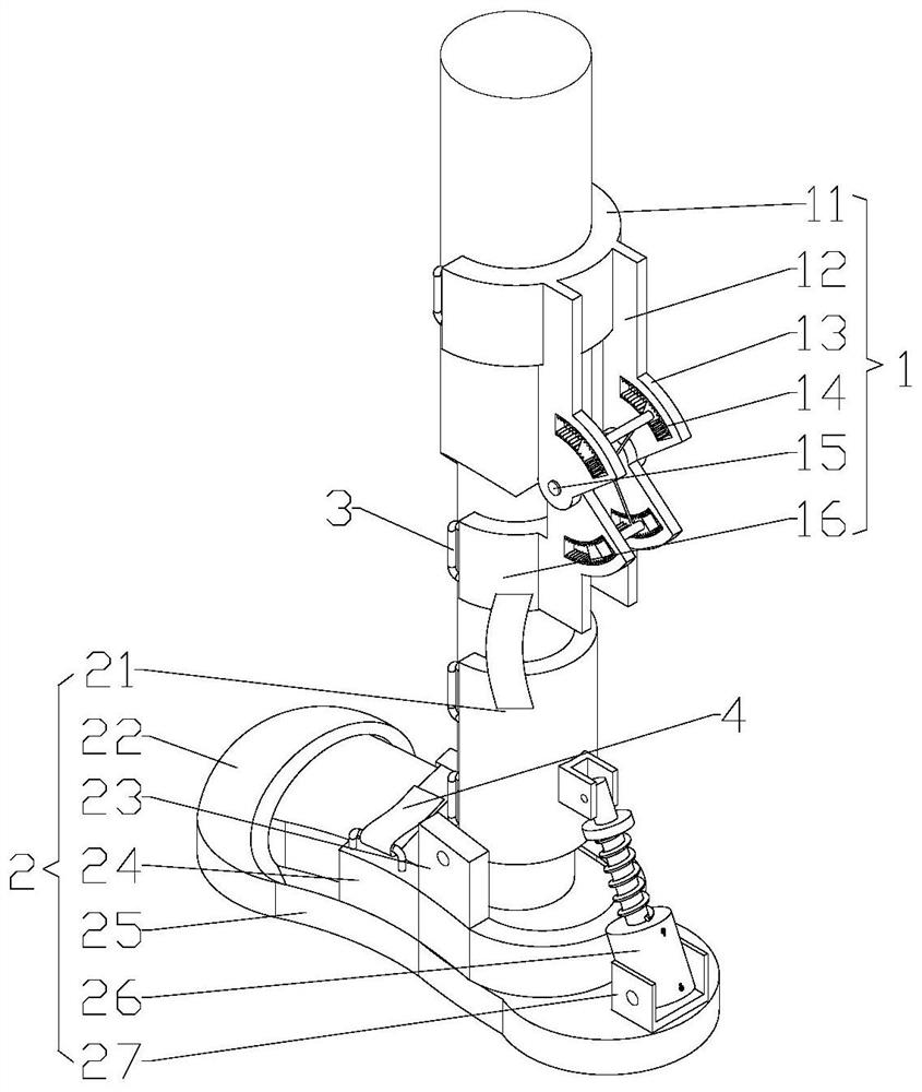
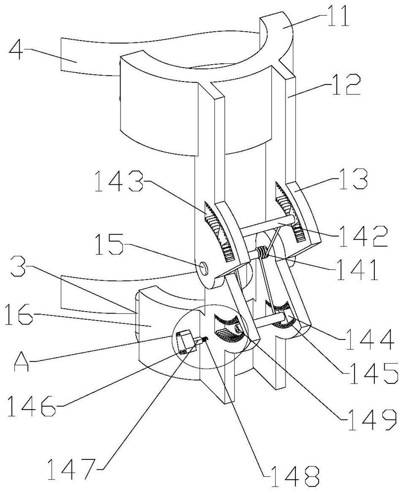
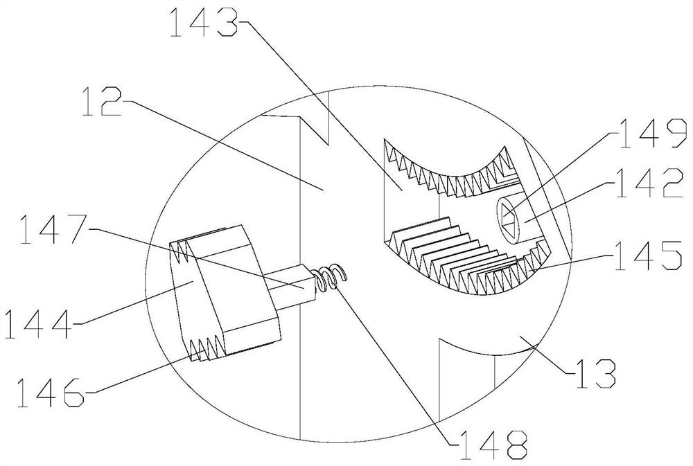
[0022] see Figure 1-4 , the present invention provides a technical solution: a new composite material joint injury support device, including a knee joint assembly 1 and a foot joint assembly 2, the knee joint assembly 1 includes a thigh ring 11 and a calf ring 16, a thigh ring 11 and a calf ring The outer walls of 16 are all fixedly installed with a group of connecting plates 12, and the adjacent ends of the connecting plates 12 are rotated and socketed with ...


PUM


Abstract

The invention discloses a novel composite joint injury supporting instrument. The novel composite joint injury supporting instrument comprises a knee joint assembly and a foot joint assembly, whereinthe knee joint assembly comprises a thigh ring and a shank ring, connecting plates are mounted on the outer walls of the thigh ring and the shank ring, rotating shafts are connected between the connecting plates in a sleeved mode, wing plates are arranged on the outer walls of the connecting plates, and adjusting mechanisms are mounted between the wing plates and the rotating shafts; the foot joint assembly comprises a shoe cylinder, wherein a fixing plate is hinged to the bottom of the shoe cylinder, the bottom of the fixing plate is connected with a protective edge, the protective edge is connected with the middle of a sole, a U-shaped seat is mounted at one end of the sole and the outer wall of the shoe cylinder, and a damper is mounted at the middle of the U-shaped seat; and the thighring and the shank ring are connected to the thigh and the shank of the knee in a sleeving mode respectively, rotating resistance between the connecting plates is adjusted through the adjusting mechanisms, and therefore, the knee joint requirements of different patients are met. The shoe cylinder sleeves the lower portion of the shank, the feet of the patients penetrate into a protection head andthe protective edge, and rotation between the sole and the shoe cylinder is flexibly supported through the damper. The ankle joint requirements of different patients are met.

Description

technical field [0001] The invention relates to the technical field of medical devices, in particular to a novel composite material joint injury support device. Background technique [0002] For patients with broken legs, sprains, and arthritis, the post-injury treatment and rehabilitation process is relatively difficult, and due to soft tissue damage in the joints, some injured patients may have long-term walking pain symptoms that can last for decades, and it is easy to recur and cause old symptoms. For sprains, exoskeleton and other facilities are often used to protect the joints. However, during the rehabilitation period, patients need to perform walking rehabilitation training to exercise the joints. As the rehabilitation training progresses, the activity of the patient's joints is adjusted according to the needs of different rehabilitation degrees. In order to meet the bending and rotation requirements of daily support and training, there is currently a lack of support...

Claims


Application Information

Patent Timeline
Patent Type & Authority Applications(China)
IPC IPC(8): A61F5/05A61H3/00F16F15/023F16F15/067
CPCA61F5/05A61H3/00F16F15/023F16F15/067F16F15/022A61H2003/005A61H2003/007Y02T50/40
Inventor 黄添增吴杰钟端玲李海媚
Owner 广东甲子科技有限公司
Learn More