
A solid co2 cleaning nozzle structure

A technology for cleaning nozzles and CO2, applied in the direction of spraying devices, spraying devices, etc., can solve problems such as unsatisfactory cleaning requirements, different pressures, large dry ice particles, etc., to improve the convenience and applicability of use, improve applicability, and improve The effect of cleaning effect

Active Publication Date: 2021-12-17
XIAMEN UNIV OF TECH
View PDF11 Cites 0 Cited by
  • Summary
  • Abstract
  • Description
  • Claims
  • Application Information

AI Technical Summary

Problems solved by technology

However, when cleaning other equipment, larger dry ice particles are required, and the pressure required is different. However, the size of the through hole on the existing crushing baffle is fixed, which cannot meet the cleaning requirements in different situations, and has poor applicability.

Method used


Image

  • A solid co2 cleaning nozzle structure
  • A solid co2 cleaning nozzle structure
  • A solid co2 cleaning nozzle structure

Examples


Embodiment Construction

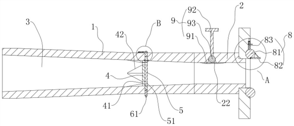
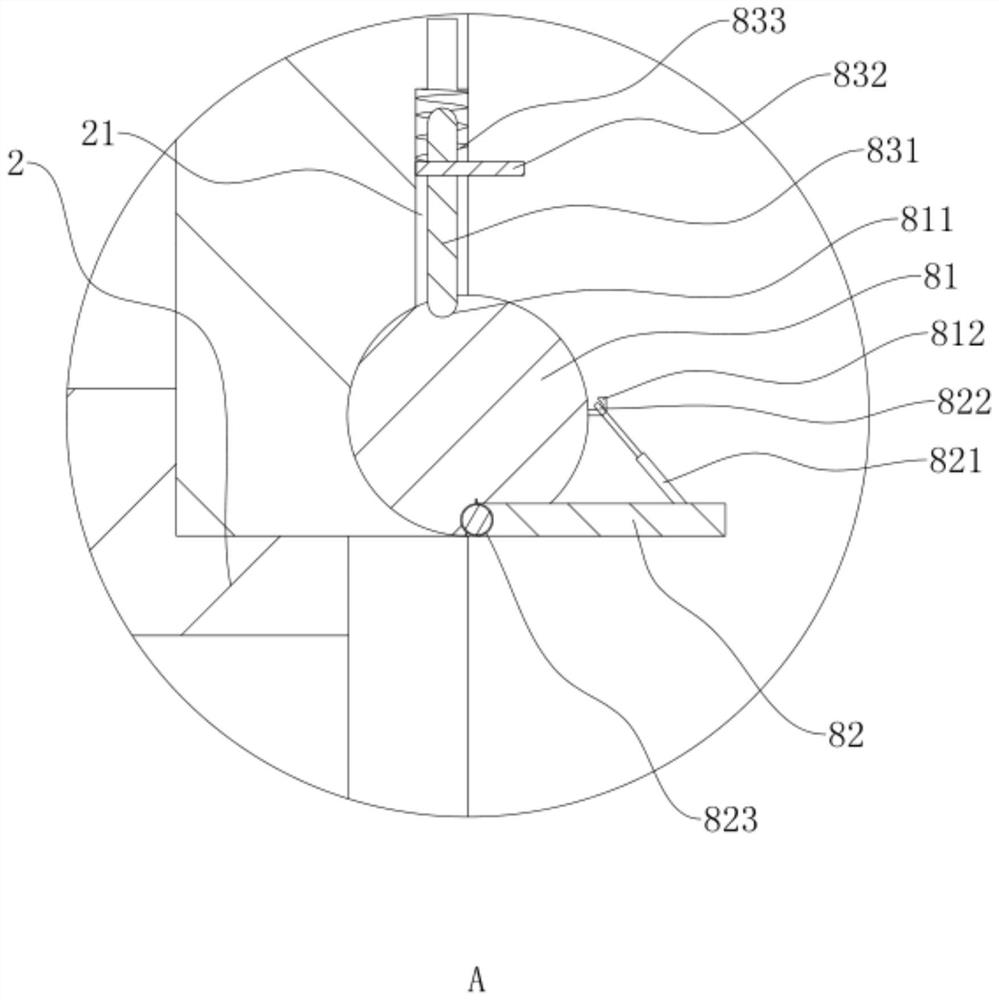
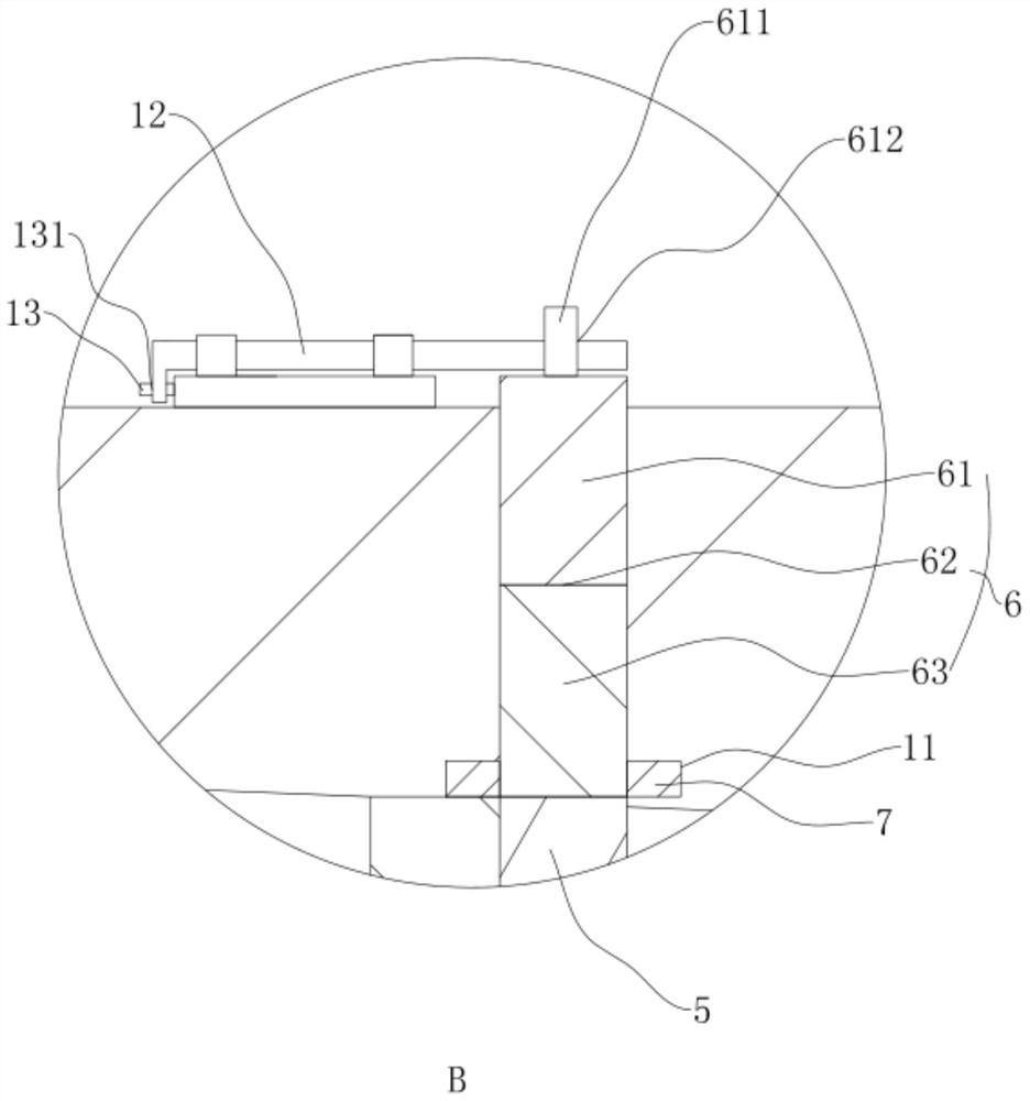
[0028] refer to Figure 1 to Figure 4 The structure of the solid CO2 cleaning nozzle is further explained.

[0029] A solid CO2 cleaning nozzle structure, such as figure 1 As shown, it includes a nozzle body 1 and a nozzle seat 2 connected to one end of the nozzle body 1. The end of the nozzle body 1 away from the nozzle seat 2 is set as the inlet side 3 for the inflow of dry ice particles and air, so as to feed in dry ice particles. Nozzle seat 2 sprays out to carry out dry ice blasting operation.

[0030] like figure 1 As shown, the end of the nozzle body 1 close to the nozzle seat 2 is provided with a crushing baffle 4, and a plurality of through holes 41 are uniformly distributed along its circumferential direction on the crushing baffle 4, so that when the dry ice passes through the through holes 41, further Cutting and refining, forming uniform dry ice particles into the nozzle seat 2 for spraying. Among them, a plurality of crushing knives 42 are uniformly arranged ...


PUM


Abstract

The invention discloses a solid CO2 cleaning nozzle structure, which relates to the technical field of dry ice cleaning. The key points of the technical solution are: comprising a nozzle body and a nozzle seat connected to one end of the nozzle body, and the end of the nozzle body away from the nozzle seat is set for On the inlet side for dry ice particles and air to flow in, the end of the nozzle body close to the nozzle seat is provided with a crushing baffle, and a hole adjustment plate is arranged on the crushing baffle, and the crushing baffle is evenly distributed along its circumference. A plurality of through holes are distributed, the hole position adjustment plate is provided with connection holes corresponding to the through holes, and no less than one adjustment hole is provided between two adjacent connection holes on the hole position adjustment plate, The diameter of the adjustment hole is smaller than that of the through hole, and the nozzle body is provided with an adjustment member for controlling the rotation of the hole position adjustment plate. The invention can adjust the size of the through hole according to the requirement of dry ice, meet various cleaning requirements, and has the effect of improving its applicability.

Description

technical field [0001] The invention relates to the technical field of dry ice cleaning, more specifically, it relates to a solid CO2 cleaning nozzle structure. Background technique [0002] The dry ice blasting machine is the most core and critical part of the dry ice blasting system, through which dry ice particles are sprayed onto the surface of the cleaning object at high speed to remove dirt. Different types of cleaning machines have different nozzle structures. Under the same conditions (air pressure, flow rate, temperature, dry ice particle size, etc.), single-throat nozzles are more efficient than double-throat nozzles. [0003] For example, the authorized announcement number is CN202021103U, and the Chinese patent announcement date is 2011.11.02 discloses a nozzle for dry ice cleaning with a crushing baffle, which is composed of a nozzle body and a nozzle seat. One end of the nozzle seat is welded to the rear end of the nozzle body. A crushing baffle is installed o...

Claims


Application Information

Patent Timeline
Patent Type & Authority Patents(China)
IPC IPC(8): B05B1/00B05B1/30
CPCB05B1/00B05B1/3006
Inventor 陈水宣董晓文洪昭斌袁和平
Owner XIAMEN UNIV OF TECH
Learn More