
Double-station laser cleaning device

A laser cleaning, dual-station technology, applied in the direction of removing smoke and dust, cleaning methods and utensils, chemical instruments and methods, etc., can solve problems such as damage to mold accuracy, poor cleaning consistency, and high noise, to prevent splashes from hurting people, improve Work efficiency, simple and reasonable structure

Pending Publication Date: 2019-09-13
南京集萃激光智能制造有限公司
View PDF0 Cites 3 Cited by
  • Summary
  • Abstract
  • Description
  • Claims
  • Application Information

AI Technical Summary

Problems solved by technology

[0002] Every year, tire manufacturers around the world manufacture hundreds of millions of tires. During the production process, tire molds must be cleaned quickly and reliably to save vulcanizer downtime. Traditional cleaning methods include sandblasting, carbon dioxide dry ice cleaning or ultrasonic cleaning, etc., but sandblasting is usually The high-heat mold must be cooled for several hours before being moved to the cleaning equipment for cleaning, which takes a long time to clean and easily damages the precision of the mold; carbon dioxide dry ice cleaning is noisy, pollutes the environment, has high carbon emissions, and poor cleaning consistency ;Chemical solvents used in ultrasonic cleaning will also cause safety and environmental protection issues; laser cleaning is booming in many fields, especially in the cleaning of tire molds. It plays an important role. It is a non-contact, safe and environmentally friendly cleaning method. Although some handheld and semi-automatic tire mold cleaning equipment have appeared on the market in recent years, there is currently a lack of an efficient automated tire mold laser cleaning equipment

Method used


Image

  • Double-station laser cleaning device
  • Double-station laser cleaning device

Examples


Embodiment Construction

[0016] The present invention will be described in further detail below in conjunction with the accompanying drawings and specific embodiments.

[0017] In the present invention, terms such as "installation", "connection", "connection" and "fixation" should be interpreted in a broad sense, for example, it can be a fixed connection or a detachable connection, unless otherwise clearly specified and limited. , or integrated; it can be mechanically connected or electrically connected; it can be directly connected or indirectly connected through an intermediary, and it can be the internal communication of two components or the interaction relationship between two components. Those of ordinary skill in the art can understand the specific meanings of the above terms in the present invention according to specific situations.

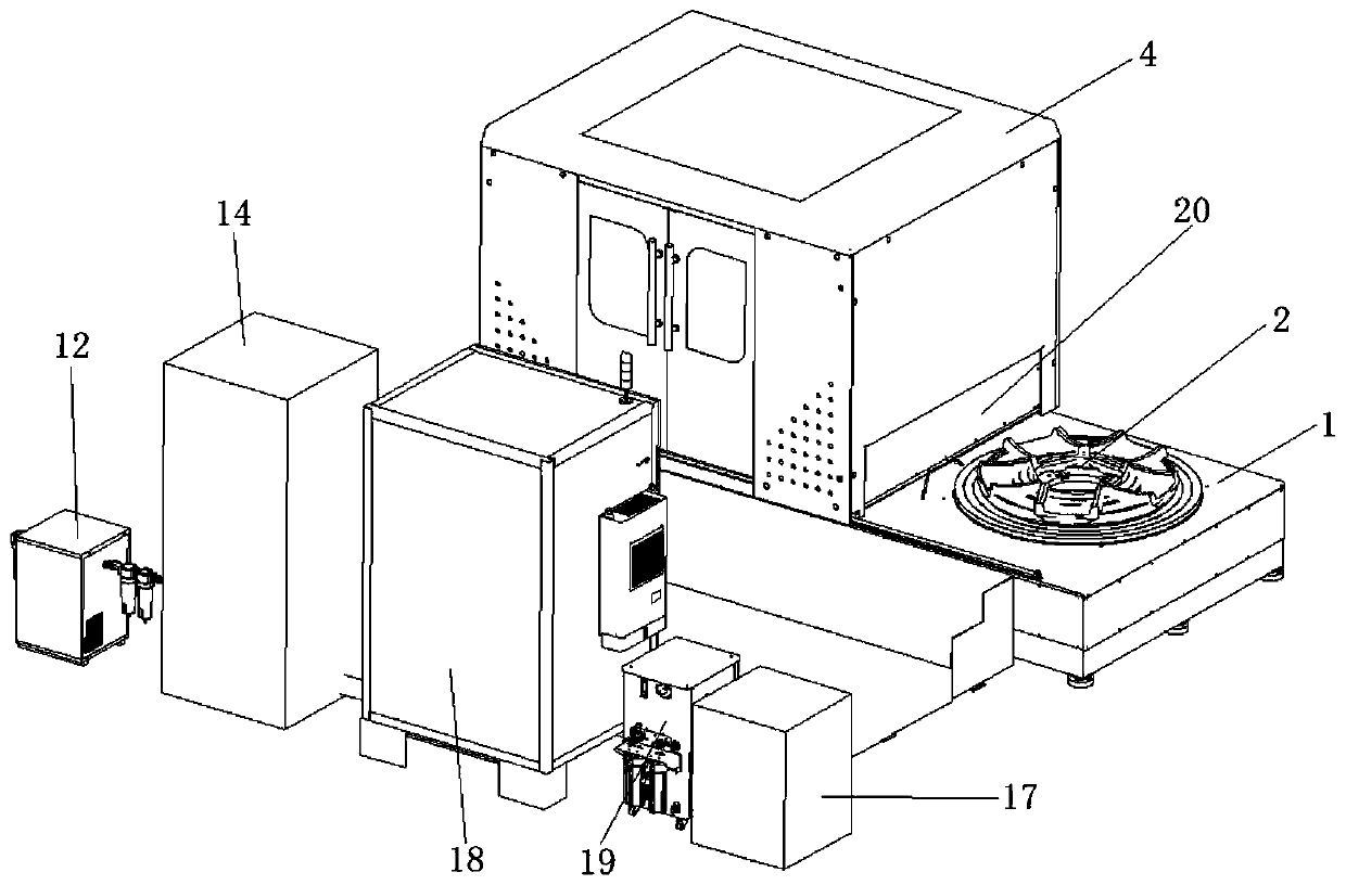
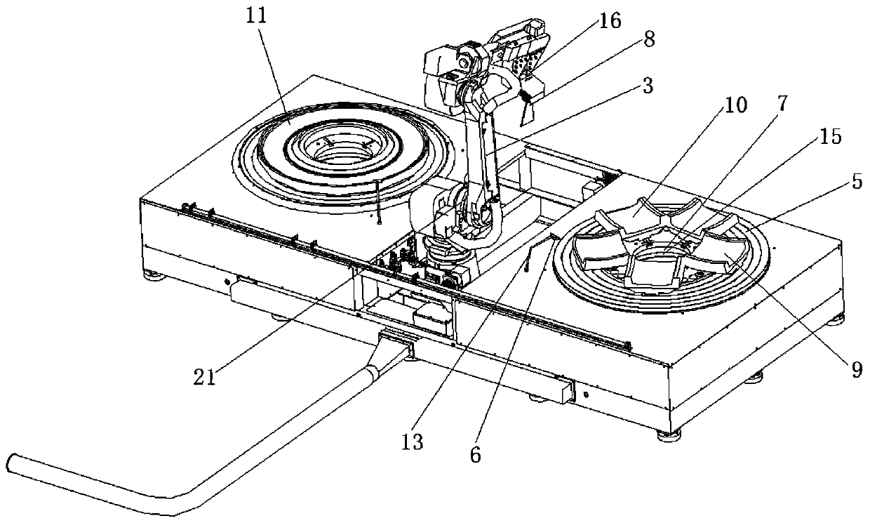
[0018] Such as Figure 1-2 As shown, it is a double-station laser cleaning equipment of the present invention, including a workbench 1, a cleaning station 2, a ...


PUM


Abstract

The invention belongs to the technical field of laser cleaning equipment, and particularly relates to a double-station laser cleaning device. The double-station laser cleaning device comprises a worktable, cleaning stations, a cleaning mechanism and a protective cover. The two cleaning stations are distributed on the work table in a left and right symmetrical manner, each cleaning station includes a rotating platform deck, each cleaning station is provided with an air blowing mechanism and an air pumping mechanism, and the cleaning mechanism is arranged between the two cleaning stations; thecleaning mechanism includes laser cleaning heads capable of moving and rotating above the cleaning stations; and the protective cover covers the outer sides of one cleaning station and the cleaning mechanism, the protective cover is slidably connected with the work table, and the protective cover can be moved from one cleaning station to the other cleaning station. The double-station laser cleaning device greatly improves the work efficiency, reduces the production cost and has the advantages of being simple and reasonable in structure, convenient to operate, high in work efficiency, safe, reliable and the like.

Description

technical field [0001] The invention belongs to the technical field of laser cleaning equipment, and in particular relates to a double-station laser cleaning equipment. Background technique [0002] Every year, tire manufacturers around the world manufacture hundreds of millions of tires. During the production process, tire molds must be cleaned quickly and reliably to save vulcanizing machine downtime. Traditional cleaning methods include sandblasting, carbon dioxide dry ice cleaning or ultrasonic cleaning, etc., but sandblasting is usually The high-heat mold must be cooled for several hours before being moved to the cleaning equipment for cleaning, which takes a long time to clean and easily damages the precision of the mold; carbon dioxide dry ice cleaning is noisy, pollutes the environment, has high carbon emissions, and poor cleaning consistency ;Chemical solvents used in ultrasonic cleaning will also cause safety and environmental protection issues; Laser cleaning is b...

Claims


Application Information

Patent Timeline
IPC IPC(8): B08B7/00B08B15/02
CPCB08B7/0042B08B15/02
Inventor 华建民杨和逸潘济堂董泽富李兴财
Owner 南京集萃激光智能制造有限公司
Learn More