High-pressure water storage tank

A water storage tank and high-pressure technology, which is applied in the direction of containers, mixers, large containers, etc., can solve the problems of limited service life of water storage tanks, inability to completely discharge water, and high cost of use by consumers, so as to reduce production input costs and save Post-maintenance costs and the effect of improving water safety

Inactive Publication Date: 2021-01-08
潘军
View PDF0 Cites 2 Cited by
  • Summary
  • Abstract
  • Description
  • Claims
  • Application Information

AI Technical Summary

Problems solved by technology

[0004] (1) Diaphragm-type and airbag-type high-pressure water storage tanks are mostly installed with a base when in use, and the base and the water storage tank are of an integrated structure. However, due to the limited service life of the water storage tank, it needs to be replaced every two or three years. The separation of the water storage tank is more difficult, so the base also needs to be replaced together, and the later use cost of consumers is higher;
[0005] (2) Diaphragm-type and airbag-type high-pressure water storage tanks rely on changes in pressure to complete the function of water inflow or outflow during use. When the pressure increases to a certain level, it will no longer enter water. No more water will come out, so the water in the water storage tank cannot be completely discharged, and the water with a low water level will accumulate in the water storage tank for a long time, which is easy to breed a large number of bacteria and affect the water safety of consumers

Method used


Image

  • High-pressure water storage tank
  • High-pressure water storage tank
  • High-pressure water storage tank

Examples


Embodiment Construction

[0030] The embodiments of the present invention will be described in detail below with reference to the accompanying drawings, but the present invention can be implemented in many different ways defined and covered by the claims.

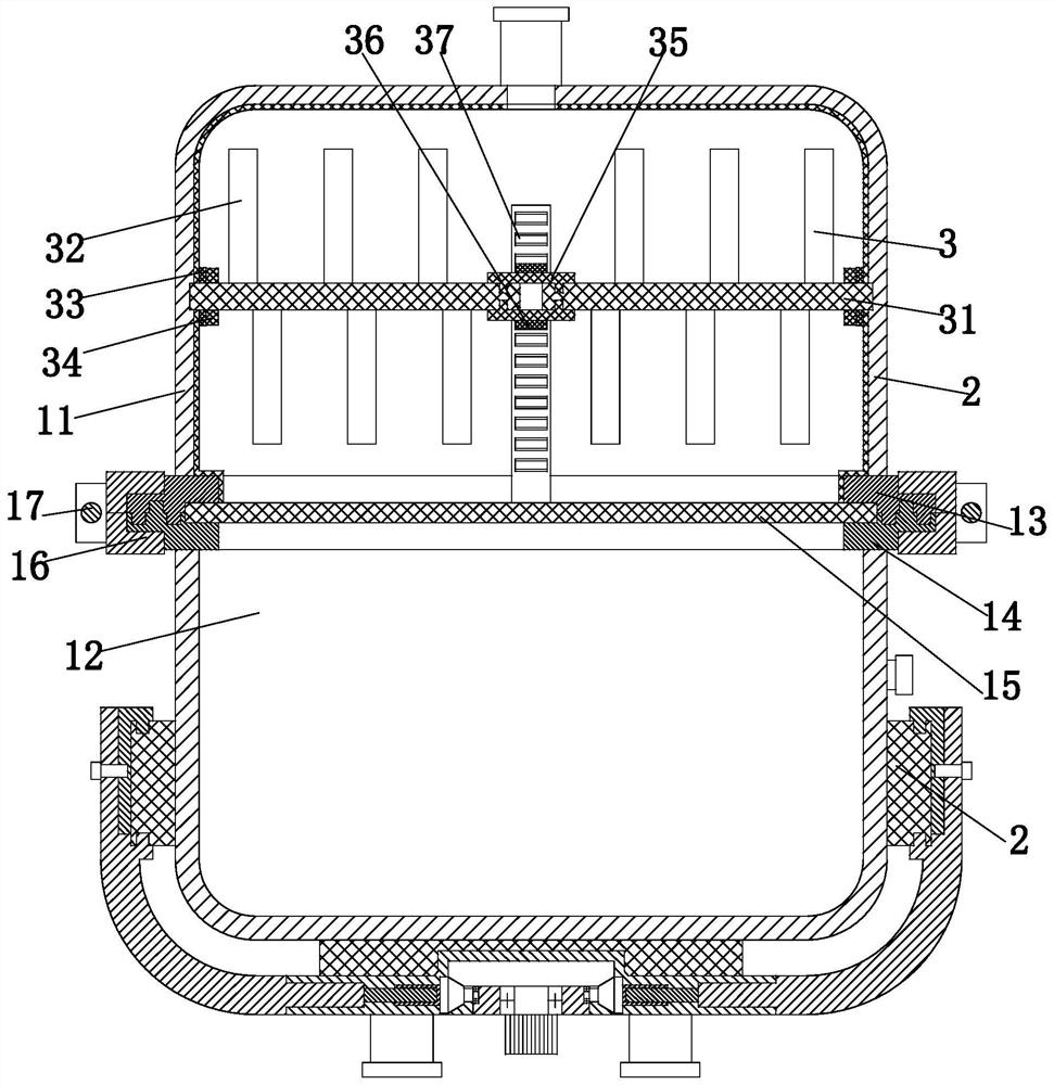
[0031] Such as Figure 1 to Figure 8 As shown, a high-pressure water storage tank includes a main body 1, a base 2 and a stirring mechanism 3, the base 2 is installed at the bottom of the main body 1, the stirring mechanism 3 is installed inside the main body 1, and a water outlet is opened at the top of the main body 1. 1 There is an air supply port at the lower end; among them:

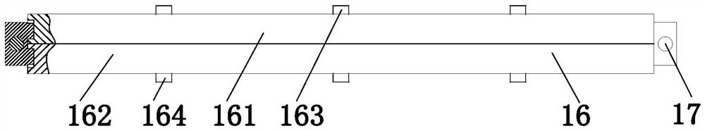
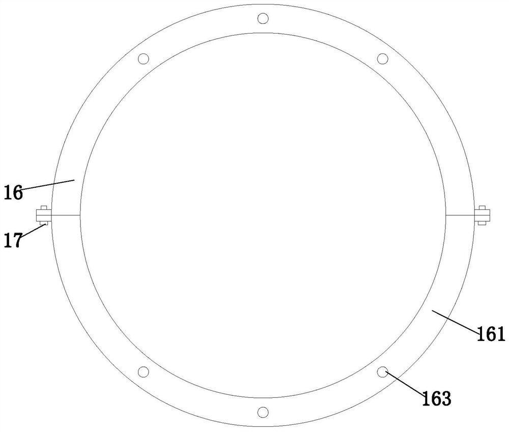
[0032] The main body 1 includes an upper shell 11, a lower shell 12, an upper docking ring 13, a lower docking ring 14, a diaphragm 15, a locking half ring 16 and a fixing bolt 17, and the upper shell 11 and the lower shell 12 are arranged opposite to each other up and down. , the upper butt ring 13 is installed at the bottom of the upper housing 11, the lower butt ring ...


PUM


Abstract

The invention relates to high-pressure water storage tank. The high-pressure water storage tank comprises a main body, a base and a stirring mechanism; the base is installed at the bottom end of the main body; the stirring mechanism is installed inside the main body; a water passing opening is formed in the top end of the main body; an air supplementing opening is formed in the lower end of the main body; the main body comprises an upper shell body, a lower shell body, an upper butt joint ring, a lower butt joint ring, a diaphragm, locking semi-rings and fixed bolts; and the stirring mechanismcomprises a stirring rod, stirring blades, a sealing ring, pressing rings, connecting semi-rings, transmission teeth and a driving branched chain. Through the arrangement of the base which is detachably connected with the main body, the stability of the water storage tank in use is improved, and after the water storage tank main body is used for a long time, the main body can be separately replaced while the base can be repeatedly used; and the stirring mechanism arranged in the main body can stir water in the main body in the use process, so the fluidity of the water is improved, and the situation that a large amount of bacteria breed due to the fact that low-position water cannot be discharged from the water storage tank for a long time is avoided.

Description

technical field [0001] The invention relates to the field of water supply equipment, in particular to a high-pressure water storage tank. Background technique [0002] The high-pressure water storage tank is used in the closed water circulation system, which plays a role in balancing the water volume and pressure, and can avoid frequent opening of the safety valve and frequent replenishment of the automatic water replenishment valve. High-pressure water storage tanks are widely used in central air-conditioning circulating water pressure stabilization, steam water supply expansion system, heating system circulating water supply and pressure stabilization, fire water supply system water supply and pressure stabilization, frequency conversion water supply and pressure stabilization, boiler water supply, pneumatic water supply and other occasions. [0003] High-pressure water storage tanks are divided into three types: diaphragm type, air bag type and air supply type. The most c...

Claims


Application Information

Patent Timeline
Patent Type & Authority Applications(China)
IPC IPC(8): B65D90/00B01F7/04
CPCB65D90/00B01F27/70
Inventor 潘军张国华
Owner 潘军
Why Eureka
Try Eureka