
Garment tailoring auxiliary negative pressure clamping device

A clamping device and clothing technology, applied in the cutting of textile materials, textiles and papermaking, etc., can solve the problems of reducing the yield of cloth cutting, reducing the cutting precision of the cloth, and the cloth is easy to form wrinkles, etc., so as to increase the cutting and clearing effect, increase the Cutting precision and cutting efficiency, the effect of increasing the leveling range

Active Publication Date: 2021-01-08
宣恩县众仁服饰有限公司
View PDF6 Cites 1 Cited by
  • Summary
  • Abstract
  • Description
  • Claims
  • Application Information

AI Technical Summary

Problems solved by technology

[0006] In order to make up for the deficiencies of the existing technology, the prior art solves the problem of tensioning and fixing the cloth after the cloth is absorbed by the suction cup, but the cloth cannot be fixed well only by the suction cup, which makes the cloth easy to form wrinkles, reduces the cutting accuracy of the cloth, and reduces the The good rate of cloth cutting leads to the problem of waste of cloth, and the negative pressure clamping device for auxiliary clothing cutting proposed by the present invention

Method used


Image

  • Garment tailoring auxiliary negative pressure clamping device
  • Garment tailoring auxiliary negative pressure clamping device
  • Garment tailoring auxiliary negative pressure clamping device

Examples


Embodiment approach

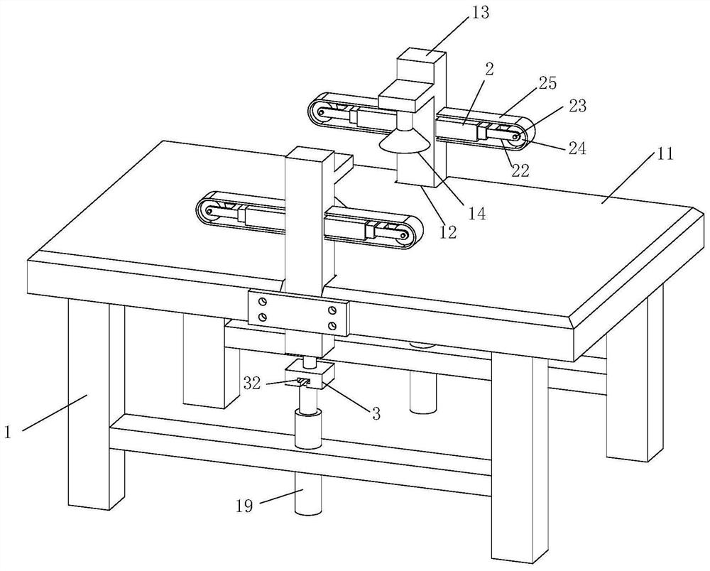
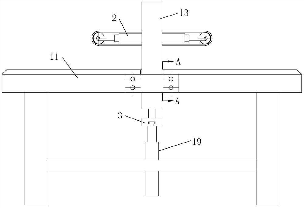
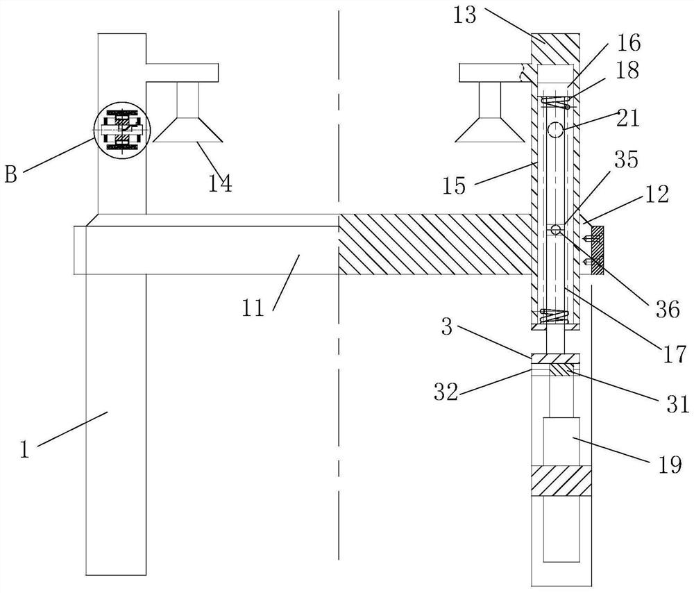
[0029] As an embodiment of the present invention, a slide table 3 and a slide block 31 are provided between the piston rod 17 and the No. 1 cylinder 19, the slide table 3 is fixedly connected with the piston rod 17, and the slide block 31 is connected to the top of the No. 1 cylinder 19. Fixed connection; the slide block 31 is slidingly connected with the trapezoidal groove 32 provided at the bottom of the slide table 3; a group of chute 33 is provided on both sides of the chute 12, and the bottom of the chute 33 is inclined to the side away from the center of the workbench 11; The position corresponding to the chute 33 on the vertical rod 13 is fixedly connected with a revolving pin 34, and the revolving pin 34 is slidably connected with the chute 33; 34 slides in the chute 33, cooperates with the sliding block 31 to slide laterally in the trapezoidal groove 32, so that the vertical rod 13 slides in a direction away from the center of the workbench 11, and further stretches th...


PUM


Abstract

The invention belongs to the technical field of garment manufacturing equipment, and particularly relates to a garment tailoring auxiliary negative pressure clamping device. The garment tailoring auxiliary negative pressure clamping device comprises a rack; a workbench is fixedly connected to the rack; vertical rods are slidably connected into sliding grooves formed in the two sides of the middleof the workbench, and suction cups are fixedly connected to the tops of the corresponding vertical rods through transverse rods; a piston and a piston rod are slidably connected into a sliding hole formed in the bottom of each vertical rod, and a reset spring sleeves the piston rod on the lower portion of each piston; a first air cylinder is fixedly connected between the bottom of each piston rodand the rack; telescopic rods are fixedly connected to the positions, corresponding to the suction cups, of the two sides of the vertical rod and communicate with the sliding holes through vent holes;the end, away from the vertical rod, of each telescopic rod is rotationally connected with a guide wheel through a support and a rotating shaft, each guide wheel is sleeved with an elastic belt, andthe two ends of each elastic band are fixedly connected with the corresponding vertical rod. Compressed air generated in the sliding holes is inflated into the telescopic rods through the vent holes,then the telescopic rods drive the guide wheels to extend towards the two sides of the vertical rods, the extended elastic belts are matched to flatten and press cloth, and the wrinkle rate of the cloth is reduced.

Description

technical field [0001] The invention belongs to the technical field of garment manufacturing equipment, in particular to a negative pressure clamping device for garment cutting assistance. Background technique [0002] In the garment processing process, the most steps are cutting and sewing. The staff puts the prepared fabric on the workbench for operation, but the fabric needs to be fixed, and pressing it with heavy objects will inevitably bring inconvenience to the operation and affect the safety of the staff. work efficiency, and it is difficult to ensure that the whole piece of fabric is completely flat, which is likely to cause garment scrapping. [0003] There are also some technical solutions about negative pressure clamping devices in the prior art. For example, a Chinese patent with application number 2018108860061 discloses a fabric negative pressure clamping device for garment cutting machine, which includes a shell, and the inside of the shell is equipped with a ...

Claims


Application Information

Patent Timeline
Patent Type & Authority Applications(China)
IPC IPC(8): D06H7/00
CPCD06H7/00
Inventor 范波芳
Owner 宣恩县众仁服饰有限公司
Learn More