A liquid rocket engine gas conduit integrated structure

A liquid rocket and engine technology, applied in the direction of rocket engine devices, machines/engines, mechanical equipment, etc., can solve problems such as no explanation or report found, and data not yet collected, so as to reduce control torque, control difficulty, and height. Effect

Active Publication Date: 2021-07-30
北京天兵科技有限公司
View PDF0 Cites 0 Cited by
  • Summary
  • Abstract
  • Description
  • Claims
  • Application Information

AI Technical Summary

Problems solved by technology

[0003] At present, there is no description or report of similar technology of the present invention found in China, and similar data at home and abroad have not been collected yet.

Method used


Image

  • A liquid rocket engine gas conduit integrated structure
  • A liquid rocket engine gas conduit integrated structure
  • A liquid rocket engine gas conduit integrated structure

Examples


Embodiment Construction

[0022] In order to make the object, technical solution and advantages of the present invention clearer, the present invention will be further described in detail below in combination with specific embodiments and with reference to the accompanying drawings. It should be understood that these descriptions are exemplary only, and are not intended to limit the scope of the present invention. Also, in the following description, descriptions of well-known structures and techniques are omitted to avoid unnecessarily obscuring the concept of the present invention.

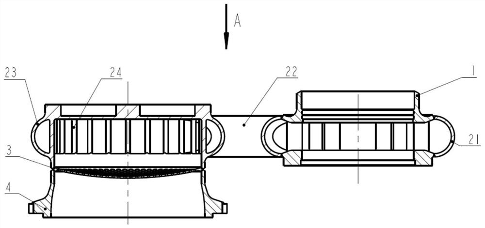
[0023] The invention provides an integrated structure of a gas conduit for a liquid rocket engine, which combines figure 1 , 2 , including sequentially connected: turbine housing 1, gas conduit collector 2, rectifying grid 3 and thrust chamber head inlet 4.

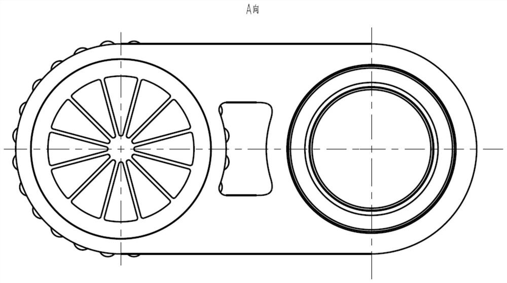
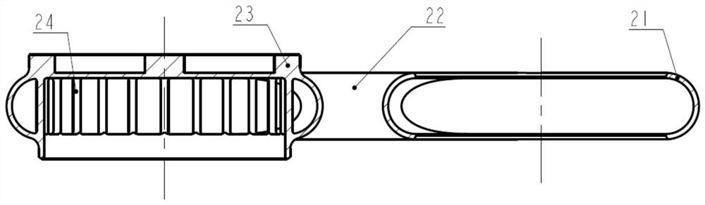
[0024] combine image 3 , 4 , the gas pipe collector 2 is provided with a gas collection ring 21, a gas pipe 22, a collection ring 23 and a diversion column 24, ...


PUM


Abstract

The invention provides an integrated structure of a gas conduit for a liquid rocket engine, which includes sequentially connected: a turbine casing, a gas conduit collector, a rectifying grid, and a thrust chamber head inlet; the gas conduit collector is provided with a gas collecting ring, a gas conduit , collection ring and diversion column, gas pipes are symmetrically scattered on both sides of the gas collection ring and dispersion ring, presenting a flat structure. The high-temperature gas enters the thrust chamber head evenly after entering the turbine shell, gas collecting ring, gas pipe, collecting ring, diversion column, rectifying grid and thrust chamber head in sequence. The technical solution adopted in the present invention has a high degree of integration, can significantly improve the compactness of the connection structure, reduce the overall height of the engine, further reduce the height of the engine connection cabin, further reduce the height of the rocket, and reduce the weight of the rocket on the one hand , on the other hand, it reduces the difficulty of rocket control. For engines used in swing, the control torque of the engine servos is also reduced.

Description

technical field [0001] The invention relates to the technical field of rocket engine equipment, in particular to an integrated structure of a liquid rocket engine gas conduit. Background technique [0002] The air intake conduit at the head of the thrust chamber and the exhaust pipe of the turbine of the traditional pump-pressed liquid rocket engine are independent structures, and the two are connected by flanges at the docking position, and a gas sealing structure is set at the connection. After the two are connected, they form a gas Catheter structure. Usually, the inlet duct at the head of the thrust chamber is in the shape of a quarter-circle elbow, which completes the direction conversion of gas from horizontal to vertical. The overall height of the engine, thereby reducing the height of the rocket engine cabin, thereby reducing the height of the entire rocket. On the one hand, the weight of the rocket is reduced, and on the other hand, the difficulty of rocket control...

Claims


Application Information

Patent Timeline
Patent Type & Authority Patents(China)
IPC IPC(8): F02K9/60
CPCF02K9/60
Inventor 沈涌斌田伟枫康永来朱正辉
Owner 北京天兵科技有限公司
Why Eureka
Try Eureka