
Wind power generation direction correcting and assisting system

A technology of a power assist system and support tower, which is applied in wind power generation, wind turbines, and wind turbines in the same direction as the wind. frequency, improve utilization rate, and improve the effect of service life

Inactive Publication Date: 2021-01-08
安徽稳行智能装备科技有限公司
View PDF0 Cites 2 Cited by
  • Summary
  • Abstract
  • Description
  • Claims
  • Application Information

AI Technical Summary

Problems solved by technology

[0004] The purpose of the present invention is to solve the existing wind power generation direction correction and boosting system. The rotating blade has a certain gravity. If the wind force is too small, the rotating blade cannot rotate quickly, or even cannot rotate. The blade does not have the function of assisting rotation, so that it can generate electricity Due to the shortcoming that the operation is limited by the larger environment, a wind power generation correction and booster system is proposed

Method used


Image

  • Wind power generation direction correcting and assisting system
  • Wind power generation direction correcting and assisting system
  • Wind power generation direction correcting and assisting system

Examples


Embodiment Construction

[0039] The following will clearly and completely describe the technical solutions in the embodiments of the present invention with reference to the accompanying drawings in the embodiments of the present invention. Obviously, the described embodiments are only some, not all, embodiments of the present invention. Based on the embodiments of the present invention, all other embodiments obtained by persons of ordinary skill in the art without creative efforts fall within the protection scope of the present invention.

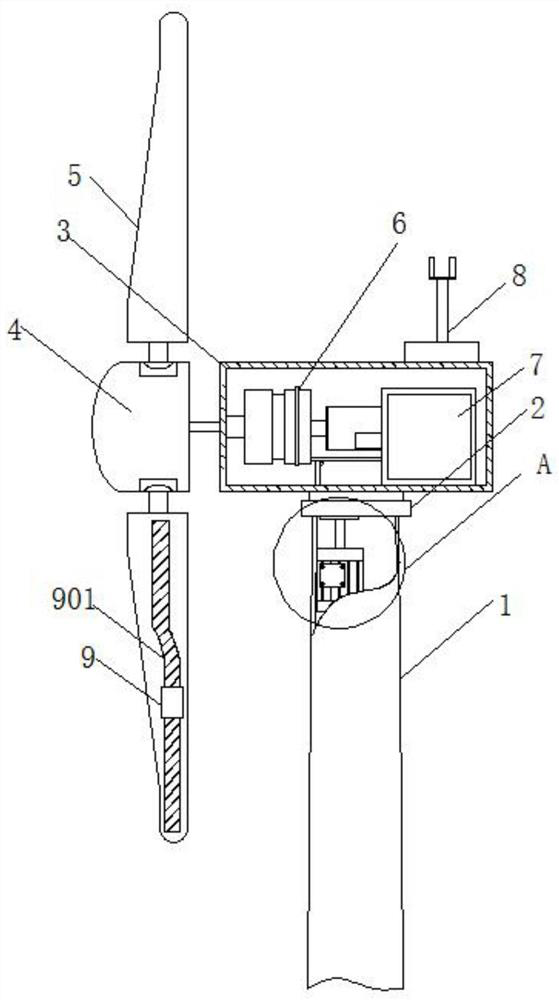
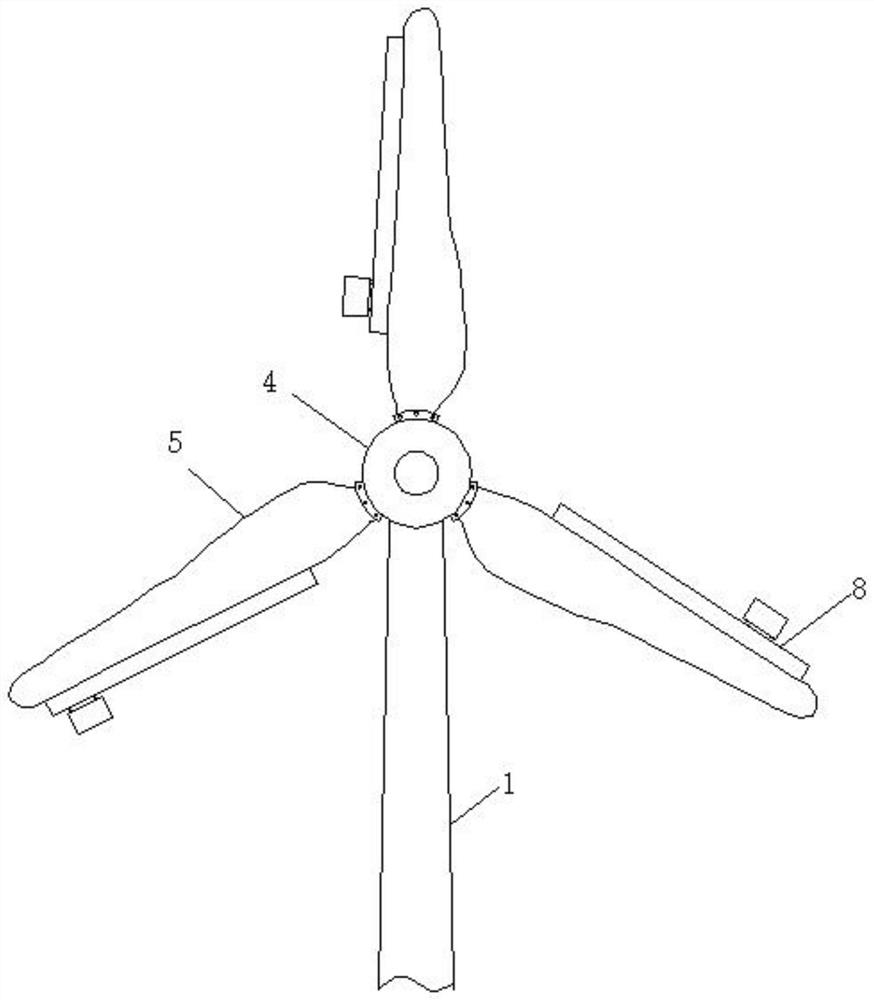
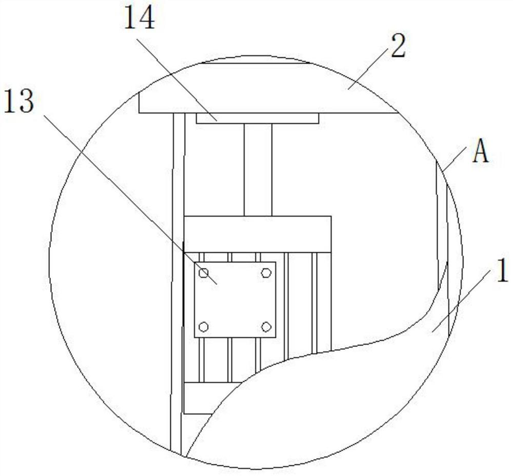
[0040] refer to Figure 1-8, a wind power generation direction correction and boosting system, comprising a supporting tower 1, a bearing 2 is fixedly connected to the top of the supporting tower 1, and the top of the bearing 2 is rotatably connected to a nacelle body 3, and one side of the nacelle body 3 is fixedly installed with The hub 4, and the surface of the hub 4 is fixedly connected with three rotating blades 5, the inside of the nacelle body 3 is installed...


PUM


Abstract

The invention discloses a wind power generation direction correcting and assisting system. The wind power generation direction correcting and assisting system comprises a supporting tower barrel, wherein the top end of the supporting tower barrel is fixedly connected with a bearing, and the top end of the bearing is rotationally connected with a cabin body; and a hub is fixedly arranged on one side of the cabin body, and the surface of the hub is fixedly connected with three rotation blades. In the wind power generation direction correcting and assisting system, when the rotation blades rotateat the low speed, rollers in a sliding rail drive a material storage groove with a plurality of balancing weights to move, the rotation blade balancing weights at the upper end slide towards the outer ends of the rotation blades, the weight of the outer ends of the rotation blades can be increased, the downward rotation speed of the rotation blades at the upper end is increased, and accordingly aplurality of rotation blades are driven through inertia to rotate in an accelerated manner. Compared with a traditional wind driven generator, the device can be used for generating power through rapid rotation of the rotation blades when wind power is small, and the wind energy utilization rate is increased; and through abutting plates and compression springs, the impact force of the rollers to the two ends of the sliding rail can be relieved, and damage caused by excessive force impacting to the rollers or the sliding rail is prevented.

Description

technical field [0001] The invention relates to the technical field of wind power generation equipment, in particular to a direction correction and boosting system for wind power generation. Background technique [0002] As a clean and renewable energy source, wind energy has attracted more and more attention from all over the world. Wind power generation refers to converting the kinetic energy of wind into electrical energy. It uses wind power to drive the windmill blades to rotate, and then increases the speed of rotation through a speed increaser. , to prompt the generator to generate electricity. [0003] The existing wind power generation direction correction and boosting system, in the process of its use, the rotating blade has a certain gravity, the wind is too small, the rotating blade cannot rotate quickly, or even cannot rotate, the blade does not have the function of assisting rotation, so that it can generate electricity The job is limited by a larger environmen...

Claims


Application Information

Patent Timeline
Patent Type & Authority Applications(China)
IPC IPC(8): F03D7/04F03D1/06F03D80/70F03D80/55F03D13/10F03D9/16
CPCF03D1/0675F03D7/0204F03D7/0276F05B2270/602F03D9/16F03D13/10F03D80/55F03D80/70Y02E10/72Y02E60/16Y02E70/30
Inventor 王利
Owner 安徽稳行智能装备科技有限公司
Learn More