Electronic water pump

An electronic water pump and pump cover technology, applied in the field of auto parts, can solve the problems of wear of the rotating shaft and the shaft sleeve, reduce the service life, difficult to eliminate, etc., and achieve the effect of prolonging the service life, speeding up the flow rate, and improving the cleaning effect.

Pending Publication Date: 2021-01-08
RUILI GROUP RUIAN AUTO PARTS CO LTD
View PDF1 Cites 0 Cited by
  • Summary
  • Abstract
  • Description
  • Claims
  • Application Information

AI Technical Summary

Problems solved by technology

The above-mentioned electronic water pump uses water as a lubricating medium between the rotor shaft and the upper shaft sleeve to form a thin water film to reduce wear. However, since the rotor shaft and the shaft sleeve only generate radial rotating centrifugal force during operation, once sand or abrasion in the water occurs Impurities entering the water film layer will be difficult to remove, and long-term operation will cause serious wear between the shaft and the sleeve, reducing the service life

Method used


Image

  • Electronic water pump
  • Electronic water pump
  • Electronic water pump

Examples


Embodiment 1

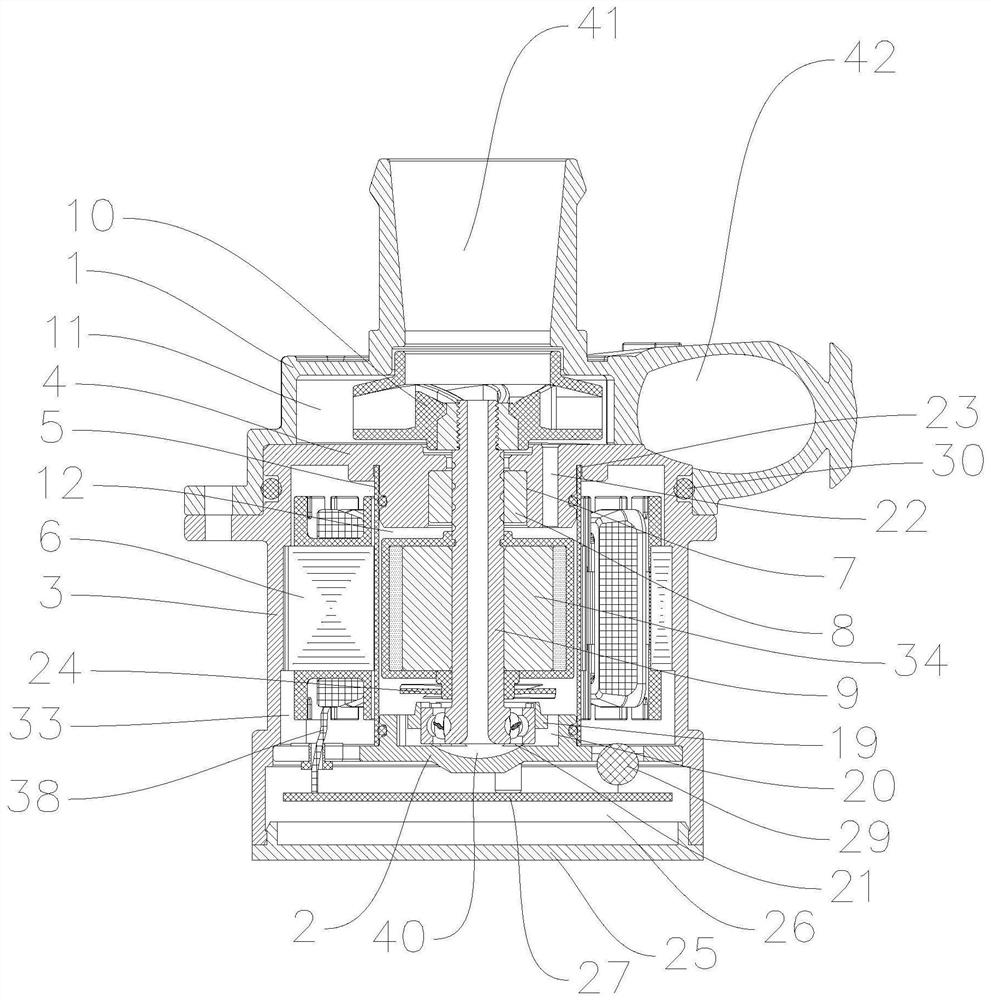
[0030] Such as Figure 1-5As shown, this embodiment discloses an electronic water pump, including: a housing, a pump cover 1 and a rear cover 2, the housing includes a housing body 3 and a housing upper cover 4, and the housing body 3 The upper cover 4 of the housing can be integrally formed or fixedly installed split type, and in this embodiment, it is integrally formed; the pump cover 1 is formed with a water inlet 41 and a water outlet 42, and the pump cover 1 1 is installed on the housing, when installed, the pump cover 1 and the housing are sealed by the pump cover sealing ring 30, and the pump cover 1 and the housing enclose the impeller cavity 11; The housing upper cover 4, the housing cylinder body 3 and the rear cover 2 enclose an accommodation cavity, and an isolation sleeve 5 is arranged in the accommodation cavity, and the isolation sleeve 5 is placed in the accommodation cavity. The fixing method inside is not specifically limited. In this embodiment, a spacer sl...

Embodiment 2

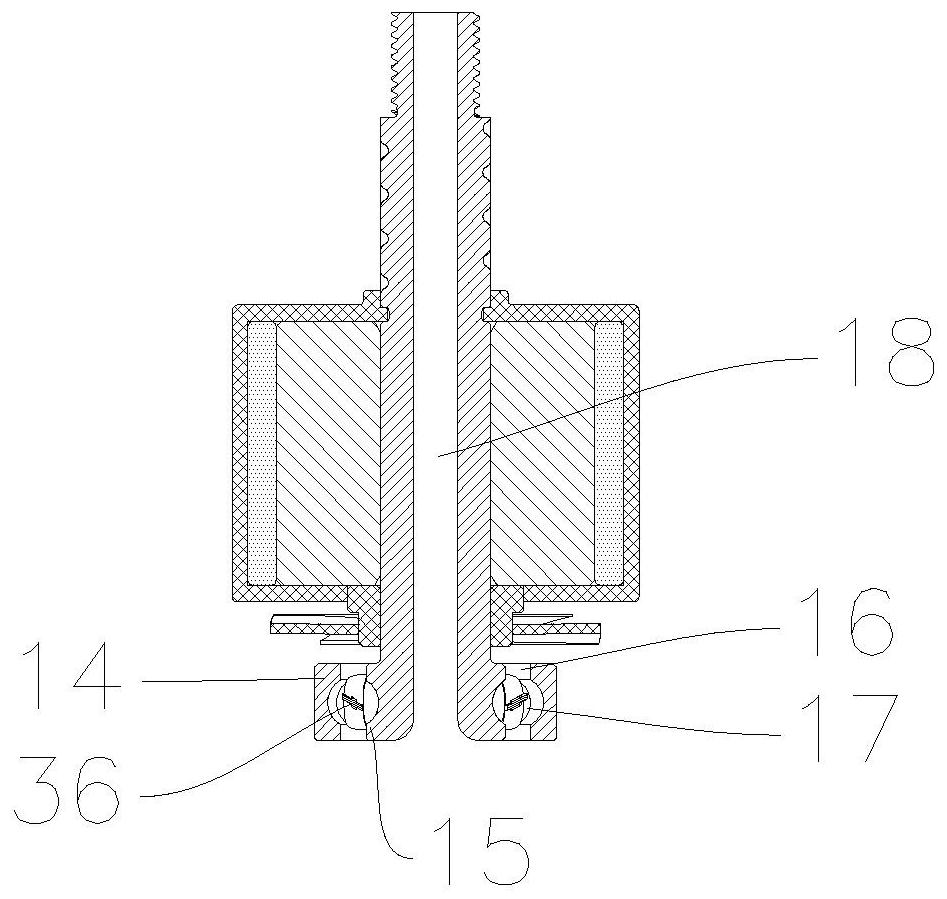
[0039] This embodiment discloses an electronic water pump, which differs from the electronic water pump provided in Embodiment 1 in that: a second helical groove is formed on the inner hole wall of the upper bushing 8 (shown in the figure). ), the helical channel is formed by the cooperation of the second helical groove (not shown in the figure) and the rotor shaft 9 .

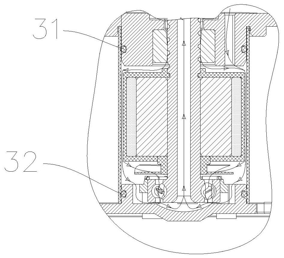
[0040] Such as Figure 1-5 As shown, when working, the stator 6 generates a magnetic field after being energized to drive the rotor block 34 and the rotor shaft 9 to rotate, and the bearing inner ring 15 also rotates accordingly; the water flow flows into the impeller from the water inlet 41 In the cavity 11, after the water in the impeller cavity 11 is stirred by the impeller 10, part of the water flow is discharged from the water outlet 42, and the other part of the water flow passes between the rotor shaft 9 and the upper bushing 8 respectively. The formed gap water flow channel and the liquid hole 22 then...


PUM


Abstract

The invention discloses an electronic water pump. The electronic water pump comprises a shell, a pump cover and a rear cover plate; the shell comprises a shell cylinder body and a shell upper cover; an upper shaft sleeve hole is formed in the shell upper cover; an upper shaft sleeve is installed in the upper shaft sleeve hole; a rotor shaft of a rotor assembly penetrates through an inner hole of the upper shaft sleeve; a gap water flow channel is formed between the rotor shaft and the upper shaft sleeve; and the two ends of the gap water flow channel are communicate with an impeller cavity anda cooling cavity respectively. Water flow in the impeller cavity flows into the cooling cavity via the gap water flow channel, when water flows through the gap water flow channel, fine gravels between the rotor shaft and the upper shaft sleeve or impurities generated by abrasion can be brought out along the gap water flow channel, and the impurities are prevented from existing in a water film layer between the rotor shaft and the upper shaft sleeve for a long time, so that abrasion between the rotor rotating shaft and a sliding bearing is reduced, and the service life of the electronic waterpump is prolonged.

Description

technical field [0001] The invention relates to the technical field of auto parts, in particular to an electronic water pump. Background technique [0002] With the rapid and sustainable development of my country's national economy, the automobile industry's vehicle consumption market and service maintenance market have developed rapidly. Energy saving and emission reduction in the automobile industry has become an important feature and strategic goal of the development of the automobile industry and the development of new energy vehicles. Therefore, the new energy auto parts industry, whose core is "lightweight, intelligent, and electronic", has developed rapidly and has become a pillar industry of the national economy and an important force driving national economic growth. As an important part of the new energy auto parts industry, automotive electronic water pumps play an important role in the development of the automotive industry. [0003] At present, electronic wate...

Claims


Application Information

Patent Timeline
Patent Type & Authority Applications(China)
IPC IPC(8): F04D13/06F04D29/04F04D29/049F04D29/043F04D29/58F04D29/70
CPCF04D13/0606F04D29/04F04D29/043F04D29/049F04D29/5886F04D29/708
Inventor 李传武朱彬余文谢宾宾贾濠宇池华许振好裴洋
Owner RUILI GROUP RUIAN AUTO PARTS CO LTD
Why Eureka
Try Eureka