Nozzle and gas stove using same

A gas stove and nozzle technology, applied in the field of gas stoves, can solve problems such as affecting air inhalation, and achieve the effects of ensuring combustion efficiency, uniform mixing, and long mixing time

Pending Publication Date: 2021-01-08
VATTI CORP LTD
View PDF0 Cites 0 Cited by
  • Summary
  • Abstract
  • Description
  • Claims
  • Application Information

AI Technical Summary

Problems solved by technology

[0003] In view of this, the object of the present invention is to provide a nozzle, which can effectively solve the problem that the existing nozzles affect the air suction due to the relatively large resistance when the air is sucked in by allowing the air to enter in a direction tangential to the circumference of the nozzle body.

Method used


Image

  • Nozzle and gas stove using same
  • Nozzle and gas stove using same
  • Nozzle and gas stove using same

Examples


Embodiment 1

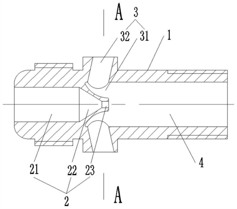
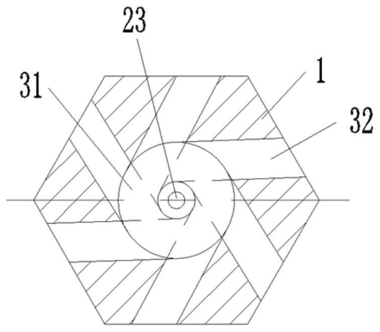
[0028] This embodiment provides a nozzle, such as Figure 1-Figure 2 As shown, it is used for a gas cooker, including a nozzle body 1, a gas inlet section 2, an air inlet section 3 and a mixing section 4; the gas inlet section 2 and the mixing section 4 are respectively arranged on the nozzle body 1 along the axial direction Both ends of the interior are connected, and the air inlet section 3 is arranged on the circumferential surface of the nozzle body 1 and communicated with the mixing section 4, so that the air enters according to the air inlet direction tangential to the circumference of the nozzle body 1;

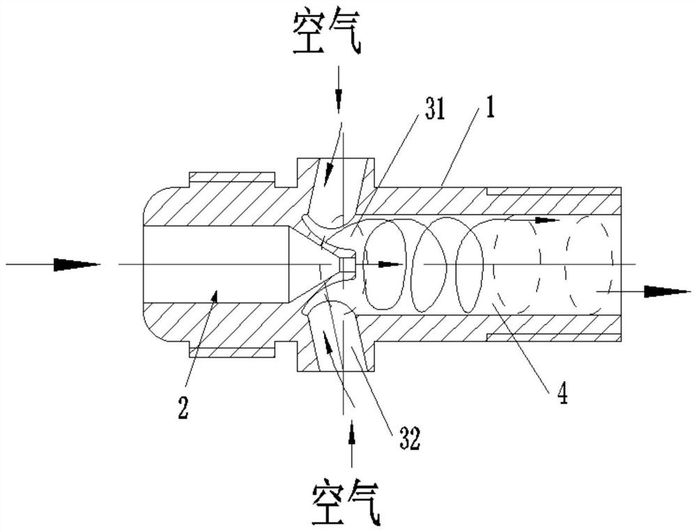
[0029] The air forms a vortex through the air inlet section 3 , and advances to the mixing section 4 in a helical rotation to mix with the gas entering through the gas inlet section 2 .

[0030] Specifically, the nozzle body 1 is an existing prism structure, the gas inlet section 2 and the mixing section 4 are respectively arranged at both ends of the nozzle body 1 alo...

Embodiment 2

[0055] This embodiment provides a gas stove using the nozzle of Embodiment 1.

[0056] In a specific implementation, the gas stove has a burner, and the end of the nozzle body 1 close to the mixing section 4 is connected to the burner.

[0057] The gas cooker of this embodiment is provided with the above-mentioned nozzle, and the gas inlet section and the mixing section connected to each other are arranged at the two axial ends of the nozzle body, and the air inlet section connected with the mixing section is arranged along the circumferential surface of the nozzle body, so that the outside air It enters in a direction tangential to the circumference of the nozzle body, and passes through the air inlet section to form a rotating air flow, that is, a vortex. The vortex rotates in a helical line in the mixing section and mixes with the gas entering through the gas inlet section. The mixing path is a spiral Ascending type, long mixing time, more uniform and thorough mixing, which...


PUM


Abstract

The invention discloses a nozzle and a gas stove using the same. The nozzle is used for the gas stove, and comprises a nozzle body, a flue gas inlet section, an air inlet section and a mixing section,wherein the flue gas inlet section and the mixing section are arranged at the two ends in the nozzle body in the axial direction respectively and communicated with each other; the air inlet section is arranged on the circumferential face of the nozzle body and communicated with the mixing section, so that air enters the nozzle body in the air inlet direction tangent to the circumferential direction of the nozzle body, forms a vortex through the air inlet section and rotationally moves forwards to the mixing section in a spiral line mode to be mixed with fuel gas entering the nozzle body through the fuel gas inlet section. According to the nozzle, the external air enters the air inlet section to form the vortex, the vortex rotationally move forwards to the mixing section in a spiral line mode to be mixed with the entering fuel gas, a mixing path is in a spiral ascending type, the mixing time is long, and mixing is more uniform and thorough, so that a problem that air suction is affected due to the fact that large resistance exists when the air is sucked into an existing nozzle is effectively solved, and the combustion efficiency of the fuel gas is guaranteed.

Description

technical field [0001] The invention belongs to the technical field of nozzle structures, and in particular relates to a nozzle and a gas stove using the same. Background technique [0002] At present, the burners of gas cooker products in my country generally adopt partial premixed air type and complete premixed air type. These two types of burners are inseparable from nozzles. The basic structure of traditional nozzles is to process a group of circular channels in a columnar body. , the circular channel includes an air inlet hole, a contraction hole, a throttle hole and an air outlet hole, and a group of air inlet holes is evenly opened around the axis of the throttle hole on the plane between the throttle hole and the air outlet hole and perpendicular to the axis of the throttle hole. This structure The nozzles make the air absorb and enter a large resistance, which will affect the inhalation of air to a certain extent. Insufficient air intake will lead to incomplete combus...

Claims


Application Information

Patent Timeline
Patent Type & Authority Applications(China)
IPC IPC(8): F23D14/48F23D14/70F23D14/02F24C3/08
CPCF23D14/02F23D14/48F23D14/70F24C3/085
Inventor 罗长兵陈琦刘凯卢华枝潘叶江
Owner VATTI CORP LTD
Why Eureka
Try Eureka