Method and device for quickly judging efficiency of new energy speed reducer

A reducer and new energy technology, which is applied in the field of automotive reducer testing equipment, can solve the problems of high cost, time-consuming sampling and inspection of the starting torque of the reducer, and the inability to timely and comprehensively monitor mass production. It achieves a unique detection method and is easy to operate. , the effect of reducing the cost of testing

Pending Publication Date: 2021-01-08
ZHUZHOU GEAR CO LTD
View PDF0 Cites 0 Cited by
  • Summary
  • Abstract
  • Description
  • Claims
  • Application Information

AI Technical Summary

Problems solved by technology

[0012] The technical problem to be solved by the present invention is: the cost of sampling and inspection of the starting torque o

Method used


Image

  • Method and device for quickly judging efficiency of new energy speed reducer
  • Method and device for quickly judging efficiency of new energy speed reducer
  • Method and device for quickly judging efficiency of new energy speed reducer

Examples


Embodiment 1

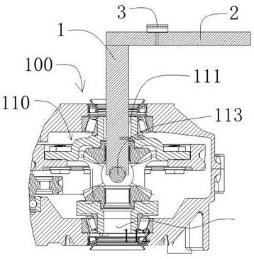
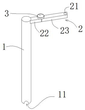
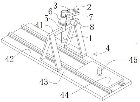
[0042] Such as figure 1 As shown in -3, a device for quickly determining the start-up efficiency of a new energy reducer designed by the above method, including a frame body 4 connecting the shaft 1, a rotating arm 2, a moment meter 3 and a uniform push arm mechanism; the frame body 4 has a seat plate 42. The lower end of the connecting shaft 1 is provided with an inverted U-shaped bayonet 11 passing through the core line of the connecting shaft 1. The inner end of the connecting shaft 1 is fixed to the rotating arm 2. The torque meter 3 is installed on the rotating arm. The push arm part of the push arm is in contact with the outer end of the connecting shaft 1; during application, the transmission is temporarily fixed on the seat plate 42 of the frame body, and the connecting shaft 1 extends into the half shaft hole 111 of the differential, and is horizontally arranged on the differential The planetary gear shaft 113 in the casing is stuck in the bayonet socket 11 of the hal...

Embodiment 2

[0050] Such as Figure 5 As shown, a device for quickly determining the start-up efficiency of a new energy reducer is different from Embodiment 1 in that the uniform-speed arm push mechanism is an active push arm mechanism, which includes a beam 41, and is arranged on the beam 41. The circular track 9 on the top, the driving wheel 10 arranged at the outer end of the rotating arm 2, and the reduction motor 8 combined with the driving wheel 10 at the outer end of the rotating arm 2; the driving wheel 10 walks on the annular track 9. When the reduction motor 8 rotates, the driving wheel 10 is driven to walk on the circular track 9 . When the power supply voltage and current of the geared motor 8 are stable, the geared motor 8 can rotate at a constant speed. Such setting is exactly that the outer end of the pivoting arm 2 walks on the circular track 9 voluntarily.

[0051] The inner circumference of the annular track 9 has inner gear teeth, and the driving wheel 10 has outer ge...


PUM


Abstract

The invention discloses a method and a device for quickly judging the efficiency of a new energy speed reducer. The device comprises a connecting shaft, a rotating arm, a torquemeter, a constant-speedpush arm mechanism and a frame body for mounting the constant-speed push arm mechanism, wherein the lower end of the connecting shaft is provided with an inverted-U-shaped bayonet passing through a shaft core line of the connecting shaft, the inner end of the connecting shaft is fixed to the rotating arm, the torquemeter is installed on the rotating arm, and a push arm component of the constant-speed push arm mechanism makes contact with the outer end of the connecting shaft. During application, the connecting shaft extends into a first half shaft hole of a differential mechanism, a planetarygear shaft transversely arranged in a shell body of the differential mechanism is clamped in the bayonet of the half shaft, the outer end of the connecting shaft is pushed by the push arm part of theconstant-speed push arm mechanism to rotate at a constant speed, and a torque value displayed by the torquemeter is read. The method and the device have the advantages that the detection method is unique, the device is simple and reasonable, the detection data can be highly approximate to the detection result of professional detection equipment, the operation is simple, convenient and rapid, thedetection cost is remarkably reduced, and all products can be monitored and detected during batch production.

Description

technical field [0001] The invention relates to speed reducer efficiency detection, in particular to a method and device for quickly determining the efficiency of a new energy speed reducer, and belongs to the technical field of automobile speed reducer detection equipment. Background technique [0002] The starting torque of the reducer is the torque required to make the rotating parts of the reducer rotate. It reflects the matching accuracy of the reducer transmission mechanism and the quality of the lubrication effect. The smaller the starting torque, the lower the useless power consumption and the efficiency of the reducer. the higher. [0003] The existing methods for judging whether the efficiency of the reducer is qualified are: [0004] 1. Select a reducer to do an efficiency test in a nationally recognized laboratory, get efficiency data, and measure the reducer [0005] The starting torque A of the reducer. Take this reducer as a reference. [0006] 2. Check th...

Claims


Application Information

Patent Timeline
IPC IPC(8): G01M13/025G01M13/027G01L3/26
CPCG01L3/26G01M13/025G01M13/027
Inventor 谢立湘刘祥环潘晓东黎超曹保平
Owner ZHUZHOU GEAR CO LTD
Why Eureka
Try Eureka