Special optical fiber guide mold for skeleton groove optical cable

A guiding mold and optical fiber guiding technology, which is applied in the field of optical cable production equipment, can solve the problems that small skeleton optical cables are of little significance and affect production efficiency, and achieve the effect of stable and reliable optical fiber arrangement and greatly increased efficiency.

Pending Publication Date: 2021-01-08
YANGTZE OPTICAL FIBRE & CABLE (SHANGHAI) CO LTD
View PDF0 Cites 0 Cited by
  • Summary
  • Abstract
  • Description
  • Claims
  • Application Information

AI Technical Summary

Problems solved by technology

However, this method is only more effective for axially linearly distributed skeleton grooves with large outer diameters and axially linearly distributed skeleton optical fibers with fiber ribbon structures, and is of little significance for axially linearly distributed small skeleton optical cables.
Due to the small outer diameter and high production speed of the first small skeleton groove during production, any force and equipment instability during the production process will cause the small skeleton groove distributed along the axial line to rotate back and forth irregularly along the axis, resulting in optical fiber It will jump out of the skeleton groove, which will cause a change in the relative position of the skeleton groove and the optical fiber, making it impossible to continue production. It needs to be stopped and rearranged, and the cycle will greatly affect the production efficiency.

Method used


Image

  • Special optical fiber guide mold for skeleton groove optical cable
  • Special optical fiber guide mold for skeleton groove optical cable
  • Special optical fiber guide mold for skeleton groove optical cable

Examples


Embodiment Construction

[0028] The present invention will be further described below in conjunction with the accompanying drawings and embodiments.

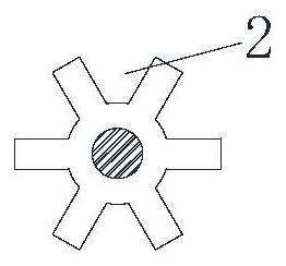
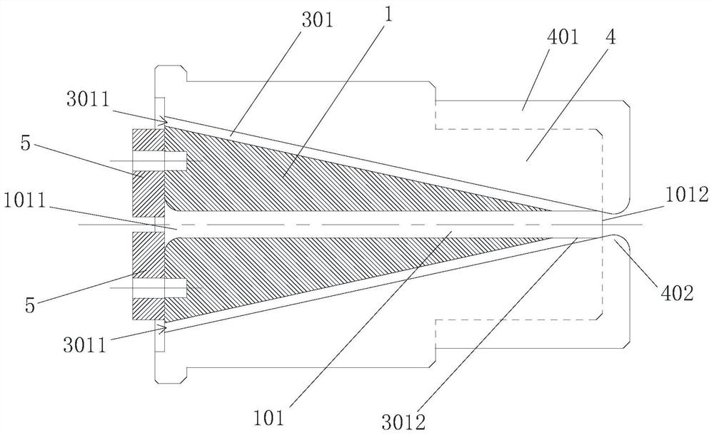
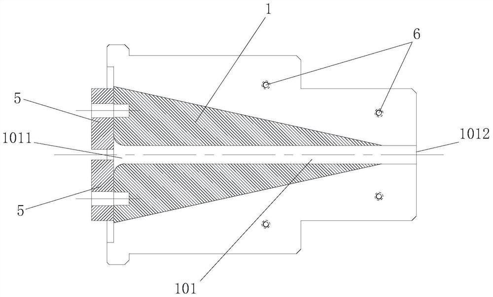
[0029] figure 2 Shown is a special optical fiber guide mold for skeleton groove optical cable, which can guide the optical fiber row to be set in the skeleton groove 2 of the skeleton, and the skeleton is evenly distributed along the circumferential direction with a number of skeleton grooves 2 extending linearly in the axial direction, such as figure 1 As shown; the fiber guide mold includes a mold main body 1, two skeleton limiters 5 and two fiber guide structures; the center of the mold main body is provided with a skeleton guide hole 101 that runs through the front and back, and the skeleton can be accommodated from the The skeleton wire inlet 1011 at the rear end of the skeleton guide hole enters and passes through the skeleton wire outlet 1012 at the front end.

[0030] Such as image 3 , Figure 4 As shown, the overall structure of the mold b...


PUM


Abstract

The invention discloses a special optical fiber guide mold for a skeleton groove optical cable. The mold comprises a mold main body, at least one skeleton limiting block and at least one optical fiberguide structure; a skeleton guide hole is formed in the mold main body; the optical fiber guide structure comprises a guide groove and an adjusting sliding block; the bottom of the guide groove inclines towards the center, and the front end of the bottom of the guide groove is connected with the framework guide hole; the adjusting sliding block is embedded in the guide groove in a matched mode and is detachably and fixedly connected with the mold main body along the guide groove in a position adjusting mode; an optical fiber guide hole cavity is formed between the adjusting sliding block andthe bottom of the guide groove; a skeleton limiting block is detachably and fixedly arranged on the rear end face of the mold main body in the mode that the position can be adjusted in the radial direction; a sharp limiting protruding block is arranged at the end, close to the skeleton guide hole, of the skeleton limiting block and matched with a skeleton groove, and a skeleton can be effectivelylimited against rotating displacement. With the guide mold adopted, an optical fiber can be stably guided into the skeleton groove of the small skeleton groove optical fiber; and the guide mold is worry-saving, labor-saving, stable and reliable.

Description

technical field [0001] The invention relates to an optical cable production equipment, in particular to an optical fiber embedding device for a skeleton groove optical cable. Background technique [0002] At present, the manufacture of skeleton optical cables generally adopts corresponding production methods for its structure. The skeleton grooves in traditional skeleton optical cables are set in a spiral manner, which leads to the need to place optical fibers in the skeleton grooves. The way of fiber stranding is to place the optical fiber in the skeleton groove, and set the pitch of the fiber stranding according to the rising angle of the skeleton groove spiral, so that the helical angle of the fiber stranding is consistent with the helix angle of the skeleton groove, so that the optical fiber matches and falls The skeleton is in the groove, and it is continuously twisted and produced in this way. For a small number of skeleton grooves distributed in a straight line in th...

Claims


Application Information

Patent Timeline
IPC IPC(8): G02B6/44
CPCG02B6/4407G02B6/4439
Inventor 符剑松
Owner YANGTZE OPTICAL FIBRE & CABLE (SHANGHAI) CO LTD
Why Eureka
Try Eureka