Camera lens with small head size

A lens and head technology, applied in the field of small head size lenses, can solve the problems of inability to reduce the size of the camera lens and the depth of the viewpoint, and achieve the effects of miniaturization, high cost performance, and small protrusions

Pending Publication Date: 2021-01-08
辽宁中蓝光电科技有限公司
View PDF0 Cites 3 Cited by
  • Summary
  • Abstract
  • Description
  • Claims
  • Application Information

AI Technical Summary

Problems solved by technology

The demand for screen-to-body ratio of smartphones is gradually increasing, but the conventional lens cannot reduce the size of the camera lens on the mobile phone screen because its lens head is too large
In addition, in

Method used


Image

  • Camera lens with small head size
  • Camera lens with small head size
  • Camera lens with small head size

Examples


Embodiment 1

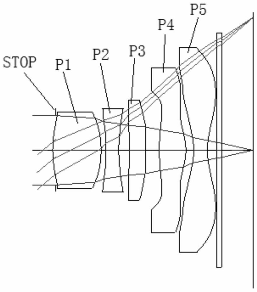
[0059] figure 1 It is a 2D diagram of the optical lens of Example 1 of the present application.

[0060] Such as figure 1 As shown, the optical lens of the present embodiment comprises in sequence from the object side to the image side along the optical axis: the first lens has positive refractive power; the second lens has negative refractive power; the third lens has positive refractive power; the fourth lens has Positive refractive power, the fifth lens has negative refractive power; the filter has object side and image side, and the aperture is set in front of the first lens. The incident light sequentially passes through the surfaces of each lens and is finally imaged on the imaging plane.

[0061] Tables 1(a), 1(b), and 1(c) show the surface type, curvature radius, thickness and material of each lens of the optical lens of Example 1. Wherein, the units of the radius of curvature and the thickness are both millimeters (mm).

[0062] Please refer to the following table...

Embodiment 2

[0078] image 3 It is the 2D figure of the optical lens given in Embodiment 2 of the present application.

[0079] Such as image 3 As shown, the optical lens of the present embodiment comprises in sequence from the object side to the image side along the optical axis: the first lens has positive refractive power; the second lens has negative refractive power; the third lens has positive refractive power; the fourth lens has Positive refractive power, the fifth lens has negative refractive power; the filter has object side and image side, and the aperture is set in front of the first lens. The incident light sequentially passes through the surfaces of each lens and is finally imaged on the imaging plane.

[0080] 2(a), 2(b), and 2(c) show the surface type, radius of curvature, thickness and material of each lens of the optical lens of Embodiment 2. Wherein, the units of the radius of curvature and the thickness are both millimeters (mm).

[0081] Please refer to the follow...

Embodiment 3

[0095] Figure 5 Embodiment 3 of the present application provides a 2D diagram of the optical lens.

[0096] Such as Figure 5 As shown, the optical lens of the present embodiment comprises in sequence from the object side to the image side along the optical axis: the first lens has positive refractive power; the second lens has negative refractive power; the third lens has negative refractive power; the fourth lens has Positive refractive power, the fifth lens has negative refractive power; the filter has object side and image side, and the aperture is set in front of the first lens. The incident light sequentially passes through the surfaces of each lens and is finally imaged on the imaging surface.

[0097] Tables 3(a), 3(b), and 3(c) show the surface type, curvature radius, thickness and material of each lens of the optical lens of Example 3. Wherein, the units of the radius of curvature and the thickness are both millimeters (mm).

[0098] Please refer to the followin...


PUM


Abstract

The invention discloses a camera lens with small head size, belongs to the technical field of optical lenses, and aims to solve the technical problem of viewpoint depth of a small-head lens while realizing miniaturization and small head size along with rapid development of a mobile phone technology and gradual development of the mobile phone lens in the direction of miniaturization and smaller head size. The optical camera lens is composed of five lenses, wherein the first lens has positive refractive power, and an object side surface of the first lens is a convex surface; the second lens element with negative refractive power has a concave image-side surface; the fourth lens element with refractive power has a convex image-side surface in a paraxial region; the fifth lens element with negative refractive power has at least one convex surface on an off-axis image-side surface; and light is imaged on the image plane after passing through an optical filter.

Description

technical field [0001] The invention belongs to the technical field of optical lenses and relates to a lens with a small head size. Background technique [0002] With the continuous upgrading of mobile phone technology, smart phones are gradually developing in the direction of larger screens and more beautiful appearance. The demand for the screen-to-body ratio of smartphones is gradually increasing, but conventional lenses cannot reduce the size of the camera lens on the mobile phone screen because the lens head is too large. In addition, in the past, the small-head lens often had a larger depth of view, resulting in a larger opening for the lens at the front of the mobile phone screen, which led to the problem of reducing the proportion of the mobile phone screen. Contents of the invention [0003] A lens with a small head size of the present invention solves the technical problem of depth of view of the small head lens while realizing miniaturization and small head siz...

Claims


Application Information

Patent Timeline
IPC IPC(8): G02B13/00G02B13/18
CPCG02B13/0045G02B13/18
Inventor 王哲金兑映葛杰
Owner 辽宁中蓝光电科技有限公司
Why Eureka
Try Eureka