
Display driving circuit and display device

A display drive and circuit technology, applied to static indicators, instruments, etc., can solve problems such as unfavorable display, low bit number, and short line scan time

Inactive Publication Date: 2021-01-08
WUHAN CHINA STAR OPTOELECTRONICS TECH CO LTD
View PDF11 Cites 1 Cited by
  • Summary
  • Abstract
  • Description
  • Claims
  • Application Information

AI Technical Summary

Problems solved by technology

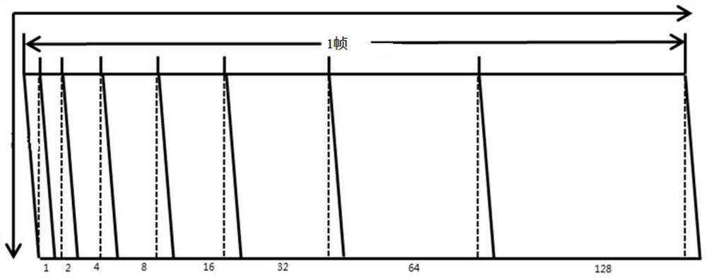
[0004] However, the time-ratio data driving method has its inherent disadvantages, because it uses the light-emitting method controlled by each subframe, the higher the resolution of the driving panel, the higher the number of color bits, and the shorter the line scanning time
The driving capability of current LTPS TFT is limited, and the resolution and number of bits that can be driven by the time ratio digital driving method are relatively low, which is not conducive to fine display

Method used


Image

  • Display driving circuit and display device
  • Display driving circuit and display device
  • Display driving circuit and display device

Examples


Embodiment Construction

[0031] The technical solutions in the embodiments of the present application will be clearly and completely described below in conjunction with the drawings in the embodiments of the present application.

[0032] In the description of this application, it should be noted that the orientation or positional relationship indicated by the terms "inner", "outer", etc. is based on the orientation or positional relationship shown in the drawings, or the usual placement of the application product when it is used. Orientation or positional relationship is only for the convenience of describing the present application and simplifying the description, and does not indicate or imply that the referred device or element must have a specific orientation, be constructed and operated in a specific orientation, and thus should not be construed as limiting the present application. Furthermore, in describing the present invention, it is to be understood that the terms "center", "longitudinal", "tr...


PUM


Abstract

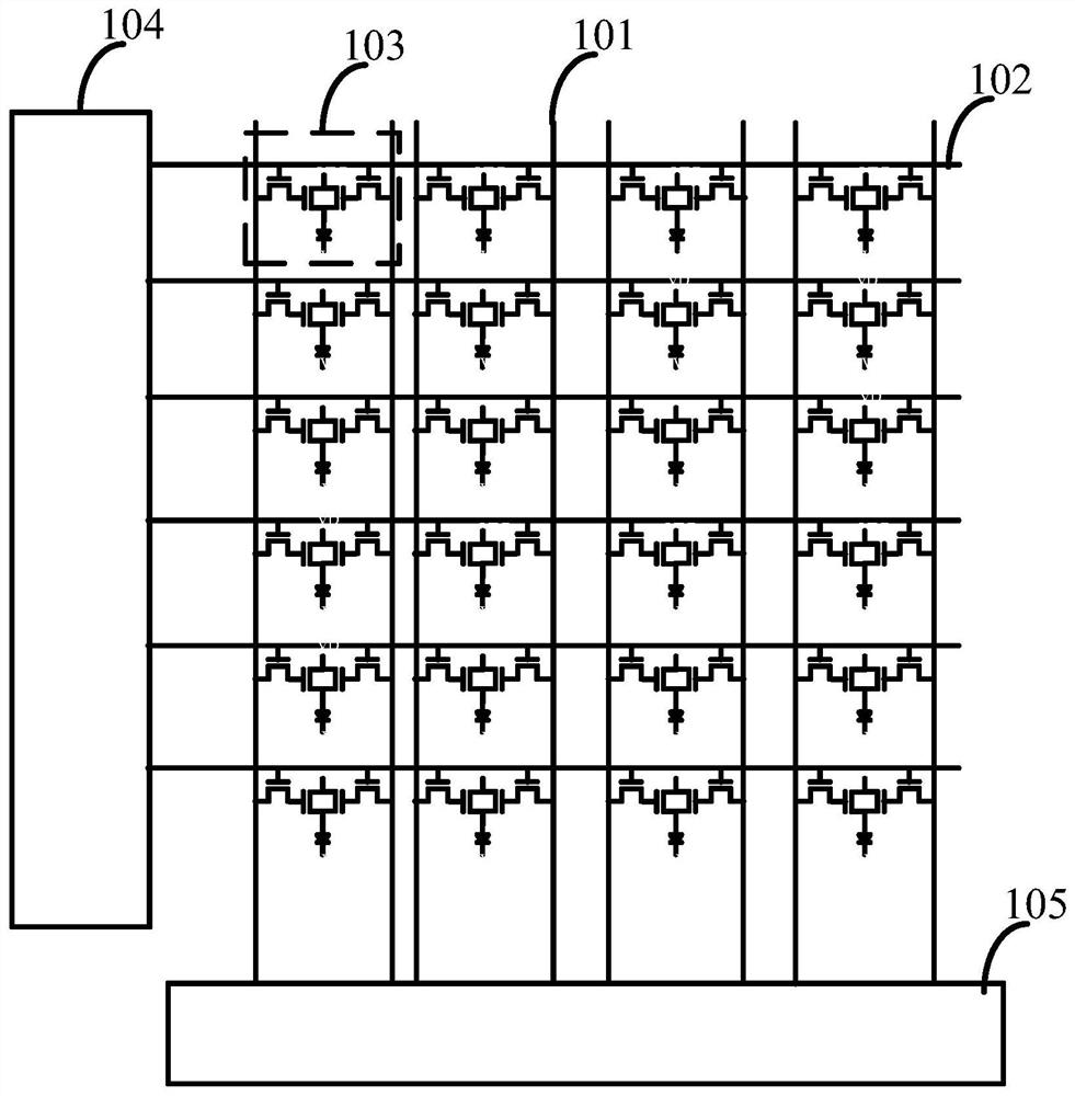
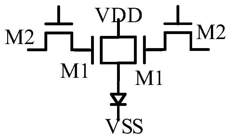
The invention provides a display driving circuit and a display device. The display driving circuit comprises a plurality of groups of data signal lines, and each group of data signal lines comprises Ndata signal lines; a plurality of gate scan lines; multiple pixel driving units, wherein each pixel driving unit comprises N first MOS tubes and N second MOS tubes, the N first MOS tubes correspond to the N second MOS tubes in a one-to-one mode, the input ends of the N first MOS tubes are connected with driving voltage, and the output ends of the N first MOS tubes are connected and used for outputting driving current to the corresponding LED light-emitting units. Gates of the N first MOS tubes are connected with output ends of the N second MOS tubes in a one-to-one correspondence manner, input ends of the N first MOS tubes are connected with the N data signal lines in the same group in a one-to-one correspondence manner, and gates of the N first MOS tubes are connected with a gate scanning line. The gray scale number of the display device can be increased, the gray scale control sensitivity can be improved, and the display quality can be improved.

Description

technical field [0001] The present application relates to the field of display technology, in particular to a display driving circuit and a display device. Background technique [0002] The current display industry is developing rapidly, and display applications have also been integrated into all aspects of people's lives. New display modes continue to emerge. The traditional LCD industry has become increasingly saturated, and the development speed has gradually slowed down. The new display methods represented by OLED, MicroLED and MiniLED are sought after by the industry and are developing rapidly. [0003] The LED display method is different from the traditional LCD display. It is a current-driven device, that is, its luminous brightness is controlled by current; while the LCD is a voltage-controlled display, and the display is realized by controlling the rotation of liquid crystal molecules by voltage. Different from voltage drive, it is more difficult to control the acc...

Claims


Application Information

Patent Timeline
Patent Type & Authority Applications(China)
IPC IPC(8): G09G3/32G09G3/3233
CPCG09G3/32G09G3/3233
Inventor 田超管延庆
Owner WUHAN CHINA STAR OPTOELECTRONICS TECH CO LTD
Learn More