Eureka AIR delivers breakthrough ideas for toughest innovation challenges, trusted by R&D personnel around the world.

Stirrer

A mixer and screen technology, which is applied to mixers with rotating stirring devices, mixers, fluid mixers, etc., can solve the problems of speeding up the rotation speed of the rotor, sucking the fluid to be processed, etc., and achieve the promotion of micro-particles, The effect of uniform particle diameter and narrow distribution of particle diameter

Pending Publication Date: 2021-01-08
M TECH CO LTD
View PDF10 Cites 0 Cited by
  • Summary
  • Abstract
  • Description
  • Claims
  • Application Information

AI Technical Summary

Problems solved by technology

Therefore, by increasing the flow rate of the intermittent jet stream discharged, the shear force between the liquid and the liquid can be increased, but there is a mechanical limit to increasing the rotational speed of the spinner.
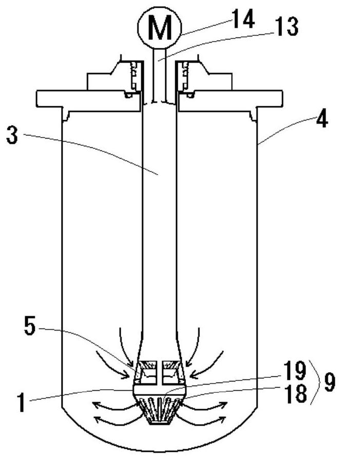
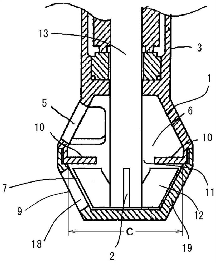
[0022] Furthermore, on the rear side of the rotation direction of the blade 12, by reducing the pressure of the fluid to be processed, a phenomenon in which the fluid to be processed is sucked in from the slit 18 on the rear side

Method used


Image

  • Stirrer
  • Stirrer
  • Stirrer

Examples


Embodiment

[0122] Hereinafter, examples and comparative examples are given to describe the present invention more specifically. However, the present invention is not limited to the Examples described below.

[0123] exist Figure 10 (A) to (C) show the shape of the cross section of the slit 18 used in the embodiment, in Figure 10 (D) shows the cross-sectional shape of the slit 18 used in the comparative example. The slit used in the embodiment is set so that the circumferential width (So) of the outflow opening 29 is smaller than the circumferential width (Si) of the inflow opening 28, and the slit used in the comparative example is the circumferential width (So) of the inflow opening 28. A slit whose upward width (Si) is the same as the circumferential width (So) of the outflow opening 29 (Si=So).

[0124] In more detail, the slits used in the examples, in Figure 10 In (A), there is a rounded corner (RO. Figure 10 In (B), the entire near-side end surface 22 is inclined forward i...


PUM

PropertyMeasurementUnit
refractive indexaaaaaaaaaa

Abstract

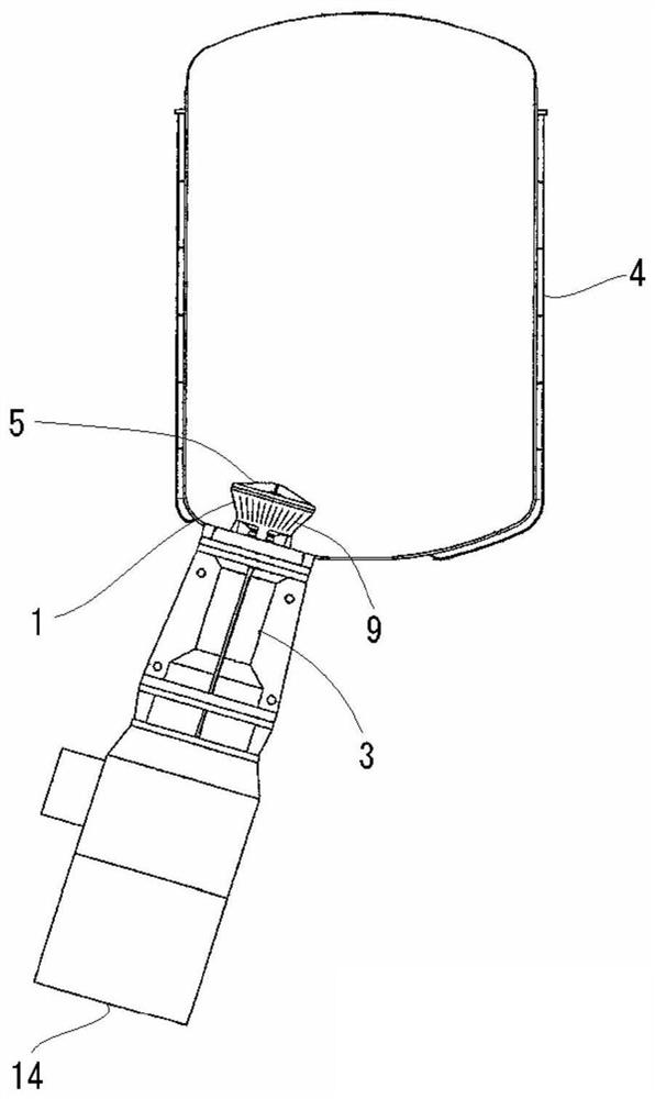
Provided is a stirrer that can more efficiently achieve shearing applied, by an action of an intermittent jet flow, to a fluid to be processed. The stirrer is characterized by concentrically comprising a rotor 2 including a blade 12, a partition wall 10, and a screen 9, wherein: the screen 9 includes a plurality of slits 18 in a circumferential direction thereof and screen members 19 located between the adjacent slits 18; by rotating at least the rotor 2 of the two components, the fluid to be processed is discharged from the inside to the outside of the screen 9 as the intermittent jet flow through the slits 18 of the screen 9; the screen 9 has a cylindrical shape having a circular cross section; an opening of the slit 18 provided on the inner wall surface of the screen 9 is used as an inflow opening 28; openings of the plurality of slits 18 provided on the outer wall surface of the screen 9 are used as outflow openings 29; and the width (So) of the outflow openings 29 in the circumferential direction is set to be smaller than the width (Si) of the inflow opening 28 in the circumferential direction.

Description

technical field [0001] The present invention relates to agitators, and in particular, relates to the improvement of agitators used for emulsification, dispersion or mixing of treated fluids. Background technique [0002] As a device for emulsifying, dispersing, or mixing treatment of fluids, various proposals have been made for mixers. However, at present, it is required to properly process fluids to be treated that contain substances with small particle diameters such as nanoparticles. . [0003] For example, a ball mill and a homogenizer are known as one of well-known mixers, emulsifiers, and dispersers. [0004] However, the ball mill has a problem in that the crystal state of the surface of the particles is broken or damaged, and the function is reduced. In addition, the problem of generation of foreign matter is also great, and the cost of frequent replacement of supplementary grinding balls is also high. [0005] In the high-pressure homogenizer, the problem of stab...

Claims


Application Information

Patent Timeline
Patent Type & Authority Applications(China)
IPC IPC(8): B01F7/16B01F5/06B01F7/22B01F7/24
CPCB01F27/8111B01F27/9214B01F23/41B01F27/84B01F27/40B01D19/0036B01D19/0047B01D19/0052B01F2215/0422B01F2215/0431B01F27/90B01F27/911B01F27/1125B01F27/1145B01F25/4523B01F25/45B01F27/91B01F27/92B01F27/9213
Inventor 榎村真一
Owner M TECH CO LTD
Why Eureka
Eureka Blog
Learn More