Cooling fin assembling machine

A heat sink and machine technology, applied in the direction of assembly machines, motor tools, metal processing, etc., can solve the problems of inconvenient handling, large floor space, and long external wiring connections, so as to avoid inconvenient collection and avoid It is easy to scratch and ensures the effect of safe use

Inactive Publication Date: 2021-01-12
安徽龙源电子集团有限公司
View PDF7 Cites 0 Cited by
  • Summary
  • Abstract
  • Description
  • Claims
  • Application Information

AI Technical Summary

Problems solved by technology

[0004] The purpose of the present invention is to provide a heat sink assembly machine, which can guarantee and solve the problem that the existing heat sink assembly machine is not convenient to be placed after the user has completed the operation, and the external wiring connection is long, which leads to a relatively large floor space. Large, inconvenient to move to different positions during use, and the problem that the skin is easy to loosen at the connection of the wire body

Method used


Image

  • Cooling fin assembling machine
  • Cooling fin assembling machine
  • Cooling fin assembling machine

Examples


Embodiment 1

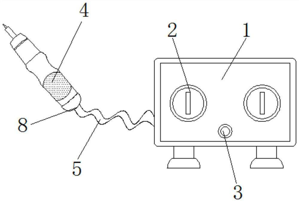
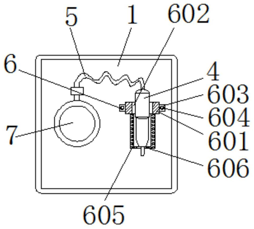
[0026] Such as Figure 1-4 As shown, the present invention provides a heat sink assembly machine, including: machine box 1, control switch 2, indicator light 3, electric screwdriver 4, connecting wire 5, placement and retention mechanism 6, fixing seat 601, built-in groove 602, installation Block 603, positioning bolt 604, placement sleeve 605, placement slot 606, storage winding mechanism 7, retaining rod 701, fixing barrel 702, rotating shaft 703, guide rod 704, guide groove 705, guide block 706, anti-loosening Mechanism 8, retaining block 801, first chute 802, first sliding block 803, fixing splint 804, first connecting piece 805, rotating post 806, second connecting piece 807, second sliding block 808, second A chute 809 and a return spring 810; a control switch 2 is installed on the front end of the machine box 1; an indicator light 3 is arranged on the outside of the control switch 2, and an electric screwdriver 4 is installed on the left side of the machine box 1; the e...

Embodiment 2

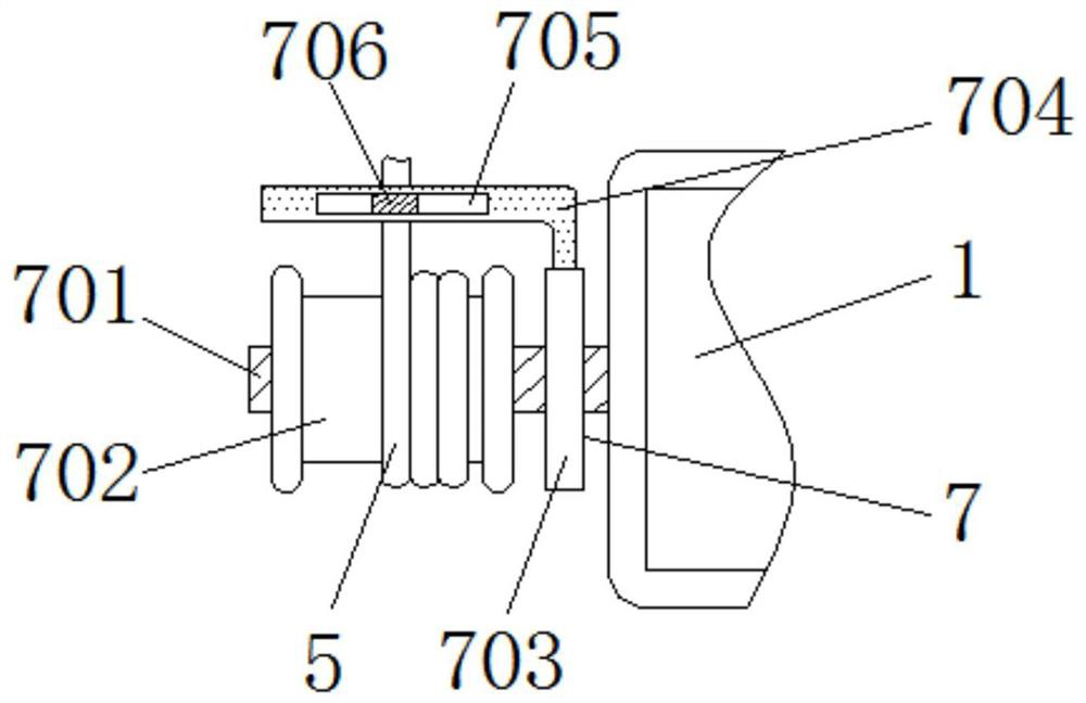
[0033] Such as figure 1 with image 3 As shown, this embodiment provides a heat sink assembly machine, which is different from Embodiment 1 in that the storage and winding mechanism 7 includes a retaining rod 701 inside; The outside of the retaining rod 701 is provided with a rotating shaft 703; the outer side of the rotating shaft 703 is equipped with a guide rod 704, and the inside of the guide rod 704 is provided with a guide groove 705; the inside of the guide groove 705 is connected with a guide block 706.

[0034] Preferably, in one of the preferred technical solutions of this embodiment, the guide block 706 forms a movable structure through the guide groove 705 and the guiding rod 704; the guiding rod 704 forms a rotating structure through the rotating shaft 703 and the retaining rod 701 .

[0035]Preferably, in one of the preferred technical solutions of this embodiment, the transverse axis of the retaining rod 701 coincides with the transverse axis of the wire fixing...

Embodiment 3

[0039] Such as figure 1 with Figure 4 As shown, this embodiment provides a heat sink assembly machine, which is different from Embodiment 2 in that the anti-loosening mechanism 8 includes a retaining block 801 inside; the retaining block 801 is provided with a first chute 802, the inside of the first chute 802 is connected with a first slider 803; the outer side of the first slider 803 is installed with a fixing splint 804, and the outside of the fixing splint 804 is connected with a first connecting piece 805; A rotating post 806 is installed on the outside of a connecting piece 805, and a second connecting piece 807 is connected to the outside of the rotating connecting piece 806; a second slider 808 is installed on the outside of the second connecting piece 807, and the A second chute 809 is arranged on the outside; a return spring 810 is installed inside the second chute 809 .

[0040] Preferably, in one of the preferred technical solutions of this embodiment, the threa...


PUM


Abstract

The invention discloses a cooling fin assembling machine. The cooling fin assembling machine comprises a machine box. Control switches are mounted on the front end surface of the machine box. An indicating lamp is arranged on the outer side of the control switch. According to the scheme, the cooling fin assembling machine is composed of the machine box, the control switches, the indicating lamp, an electric screwdriver and other components. When a user needs to assemble cooling fins, the control switch can be screwed, so that a power source of the electric screwdriver is connected, the coolingfin assembling machine starts to work, and therefore the user can operate the cooling fin assembling machine conveniently. A retention block is arranged at a wiring outlet of the electric screwdriver. A through groove is formed in the retention block, so that a wire body can be effectively connected and retained, and two groups of wire fixing clamping plates are mounted in the retention block; and the wire fixing clamping plates are reset through reset springs, so that the external connection wire body is effectively clamped and retained, and the situation that the wire body at the external connection position is pulled to get loose is effectively prevented.

Description

technical field [0001] The invention relates to the technical field of heat sink assembly, in particular to a heat sink assembly machine. Background technique [0002] The heat sink is a device for cooling the heat-prone electronic components in electrical appliances. It is mostly made of aluminum alloy, brass or bronze into plates, sheets, and multi-sheets. For example, the CPU central processing unit in a computer needs to use a large Heat sinks, power tubes in TVs, line tubes, and power amplifier tubes in power amplifiers all use heat sinks. Although the existing heat sink assembly machine uses an electric screwdriver to quickly assemble the heat sink, in actual use, when the user finishes the operation, the placement position is not well fixed; and the external wire connection is long, resulting in The placement occupies a large area, and it is inconvenient to move in different positions during use; in addition, the existing electric screwdriver is prone to loosening at...

Claims


Application Information

Patent Timeline
Patent Type & Authority Applications(China)
IPC IPC(8): B23P21/00B23P19/06B25B21/00
CPCB23P21/00B23P19/06B25B21/00
Inventor 罗玉山
Owner 安徽龙源电子集团有限公司
Why Eureka
Try Eureka