
Optical axis self-power conveying mechanism

A technology of transmission mechanism and optical axis, which is used in grinding frames, grinding/polishing equipment, and machine tools designed for grinding the rotating surface of workpieces. It can solve the problems of high energy consumption, low transmission efficiency, and high transmission equipment requirements problems, to achieve the effect of eliminating use limitations, high transmission efficiency, and simple structure

Pending Publication Date: 2021-01-12
天津天弘精工传动机械科技股份有限公司
View PDF0 Cites 0 Cited by
  • Summary
  • Abstract
  • Description
  • Claims
  • Application Information

AI Technical Summary

Problems solved by technology

[0003] During the manufacturing process of the optical axis, due to its large length, it is necessary to ensure that its surface is smooth during transmission, and that it cannot be bent to damage its strength and use effect, so the requirements for its transmission equipment are relatively high. The existing optical axis The transmission mechanism has low transmission efficiency and high energy consumption, and it cannot guarantee that the surface of the optical axis will not be damaged during the transmission process, and the height of the transportation mechanism cannot be adjusted, resulting in limitations in its use

Method used


Image

  • Optical axis self-power conveying mechanism
  • Optical axis self-power conveying mechanism

Examples


Embodiment 1

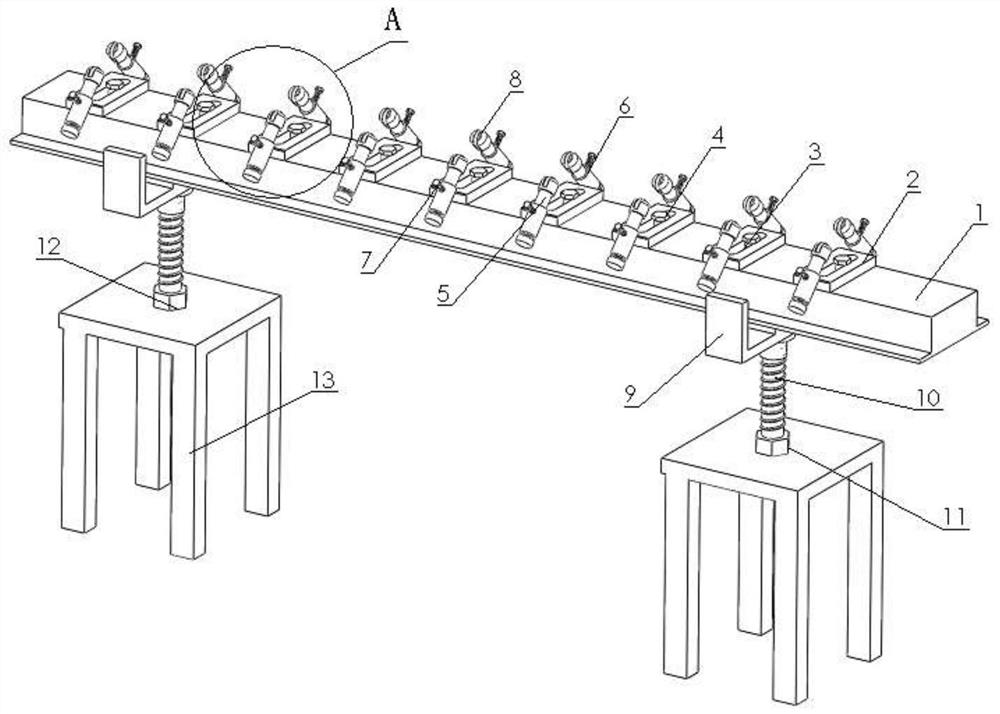
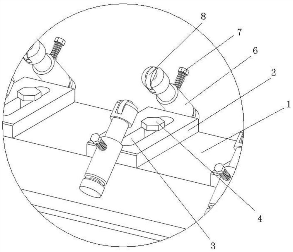
[0015] The present invention is an optical axis self-supporting transmission mechanism, which includes a transmission frame 1, a mounting base 2, a mounting groove 3, a fixing bolt 4, a left transmission column 5, a right transmission column 6, an adjustment bolt 7, a roller 8, a connecting frame 9, Supporting bolts 10, nuts 11, mounting holes 12, and supporting bases 13, the total length of the transmission frame 1 is greater than 2 meters, the transmission frame 1 is provided with mounting seats 2, and the number of mounting seats 2 is N, N≥ 8. The installation seat 2 is provided with an installation groove 3, and the installation groove 3 is provided with a fixing bolt 4, and the fixing bolt 4 passes through the installation groove 3 to fix the installation seat 2 and the transmission frame 1 together, so that The left and right transmission columns 5 and 6 are respectively arranged on the left and right sides of the mounting base 2, and the left transmission column 5 and th...

Embodiment 2

[0017] When working, one end of the mechanism is connected with the grinding machine, and the optical axis is placed on the left transmission column 5 and the right transmission column 6 of the transmission frame 1. Since there is a gap at the top of the left transmission column 5 and the right transmission column 6, the distance between the gaps is less than that of the light beam. The diameter of the shaft can ensure that the optical shaft will not fall or be clamped, resulting in the failure of transmission. Driven by the grinding mechanism of the grinding machine, the head end of the optical shaft has an initial force of rotation. The left transmission column 5, The right transmission column 6 is set in a misplaced position, which can make the optical axis move towards the grinding machine in a rotating manner. When moving, it is powered by itself and has low energy consumption. At the same time, the roller 8 is in contact with the outer periphery of the optical axis to ensu...


PUM

PropertyMeasurementUnit
Lengthaaaaaaaaaa

Abstract

The invention discloses an optical axis self-power conveying mechanism. The optical axis self-help conveying mechanism comprises a conveying frame, a mounting seat, a mounting groove, a fixing bolt, aleft conveying column, a right conveying column, an adjusting bolt, rollers, a connecting frame, supporting bolts, nuts, mounting holes and a supporting base, wherein the mounting seat is arranged onthe conveying frame, the mounting groove is formed in the mounting seat, and the fixing bolt is arranged in the mounting groove; the left conveying column and the right conveying column are arrangedon the left side and the right side of the mounting seat respectively, wherein grooves are formed in the tops of the left conveying column and the right conveying column, and the rollers are arrangedin the grooves and rotationally connected with the inner walls of the grooves through rotating shafts; the connecting frame is arranged at the bottom of the conveying frame, wherein the supporting base is arranged at the bottom of the connecting frame, and the mounting holes are formed in the supporting base; and the supporting bolts are arranged between the connecting frame and the supporting base, wherein the tops of the supporting bolts are fixedly connected with the bottom of the connecting frame, the bottoms of the supporting bolts penetrate through the mounting holes, and the nuts are arranged on the supporting bolts. The optical axis self-power conveying mechanism has the advantages of being simple in structure, high in conveying efficiency, low in energy consumption and capable ofguaranteeing that the surface of an optical axis is not damaged in the conveying process.

Description

technical field [0001] The invention relates to a transmission mechanism, in particular to an optical axis self-powered transmission mechanism. Background technique [0002] The linear optical axis is a product that has a guiding function of a sliding bearing and can perform linear motion. The necessary conditions required by these linear motion systems are: simple design, best execution ability, low maintenance cost, use of strictly selected strong and durable materials, high frequency heat treatment, accurate outer diameter size, roundness, and straightness And surface treatment, etc. Linear optical axis is widely used in many linear motion systems such as cylinder rods, automatic precision printers, automatic cutting machines and industrial robots. The common axes are crankshaft, straight axis and flexible axis. Divided into: ① Rotating shaft, which bears both bending moment and torque during work, is the most common shaft in machinery, such as the shaft in various reduc...

Claims


Application Information

Patent Timeline
IPC IPC(8): B24B5/35B24B41/02
CPCB24B5/355B24B41/02
Inventor 于涛
Owner 天津天弘精工传动机械科技股份有限公司
Learn More