Concrete stirring device for building construction

A mixing device and building construction technology, which is applied in the direction of cement mixing device, clay preparation device, cleaning method and utensils, etc., can solve the problems of increasing mixing time, reducing concrete mixing uniformity, poor mixing effect, etc., and achieve the goal of reducing maintenance and cleaning process, avoid abnormal operation, and ensure the effect of health

Inactive Publication Date: 2021-01-12
蒋俊学
View PDF0 Cites 5 Cited by
  • Summary
  • Abstract
  • Description
  • Claims
  • Application Information

AI Technical Summary

Problems solved by technology

[0003] The flow of cement inside the existing mixing device is mostly in a spiral mode. When mixing, it can only be mixed at the position of the mixing device close to the position of the mixing blade. The further outward the mixing effect is, the worse it is, thereby reducing the mixing uniformity of the concrete and increasing the mixing time.

Method used


Image

  • Concrete stirring device for building construction
  • Concrete stirring device for building construction
  • Concrete stirring device for building construction

Examples


Embodiment 1

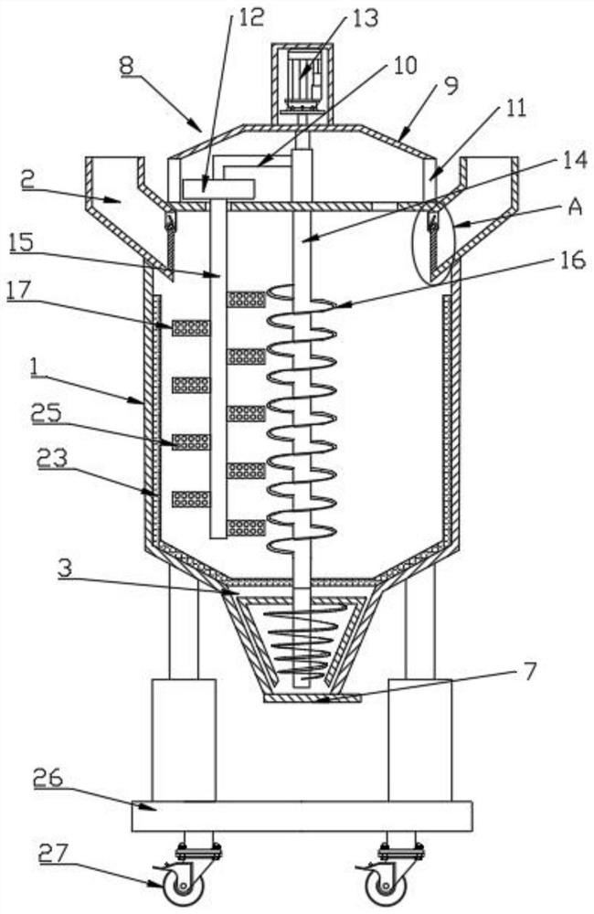
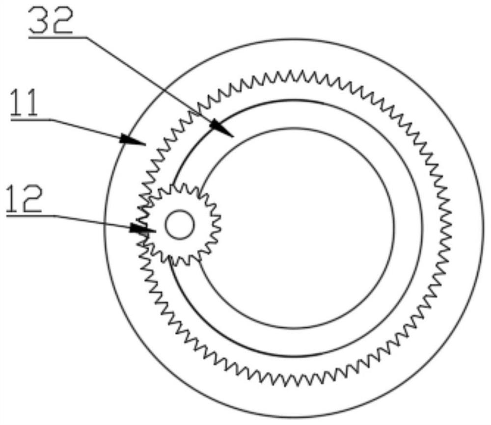
[0026] see Figure 1-5 , a concrete mixing device for building construction, comprising a mixing tank 1, the side top of the mixing tank 1 is symmetrically provided with a feed channel 2, the bottom of the mixing tank 1 is provided with supporting feet, and the center of the bottom surface of the mixing tank 1 A discharge channel 3 is provided at the bottom of the feed channel 2, an anti-splash mechanism 5 is provided at the bottom of the feed channel 2, an anti-blocking mechanism 6 is provided in the discharge channel 3, and a valve 7 is hinged at the bottom of the discharge channel 3, The top surface of the stirring tank 1 is provided with a driving mechanism 8, and the driving mechanism 8 includes a top cover 9, a deflection rod 10, a first gear 11, a second gear 12, a motor 13, a first rotating shaft 14 and a second rotating shaft 15 , the first gear 11 is fixed on the top surface of the stirring tank 1, and the first gear 11 is an internal gear, the top cover 9 is fixed o...

Embodiment 2

[0033] This embodiment has been improved on the basis of Embodiment 1, specifically:

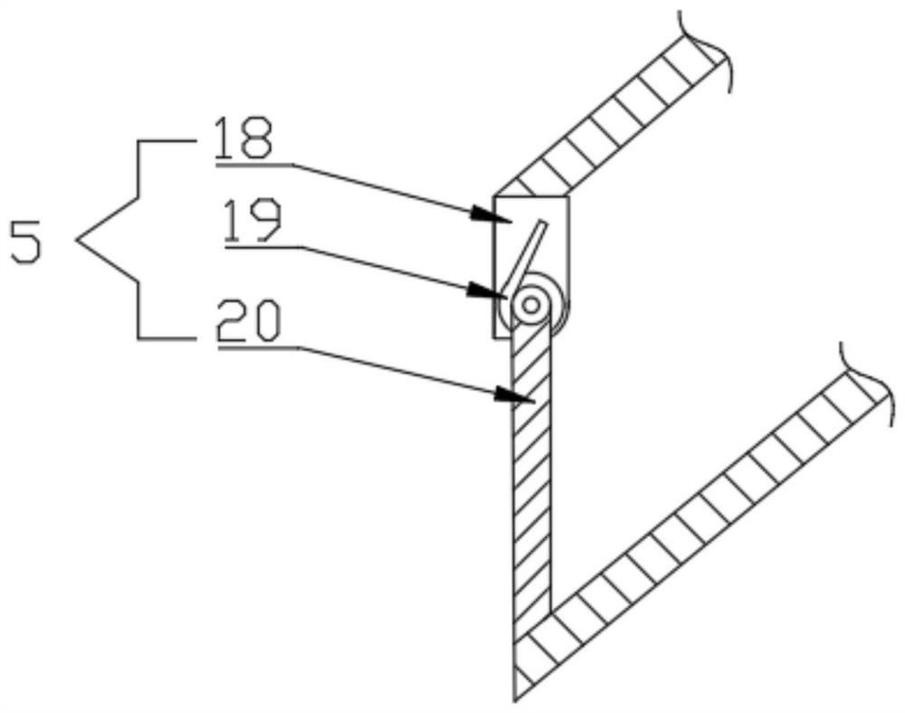
[0034]The anti-splash mechanism 5 includes a mounting base 18, a torsion spring 19 and a baffle plate 20, the mounting base 18 is fixed on the top side wall of the bottom of the feeding channel 2, and a torsion spring is movably installed on the outside of the mounting base 18 19. The outer side of the torsion spring 19 is movably equipped with a baffle 20. By setting the anti-splash mechanism 5, the concrete raw material is poured into the feed channel 2. Under the gravity of the concrete raw material, the torsion spring 19 rotates to make the baffle 20 separate, so that the raw materials enter the mixing tank 1, after the materials enter, the torsion spring 19 rotates in the opposite direction, so that the baffle plate 20 is closed again, which avoids the increase of air dust caused by the blowing of the cement by the air during the operation of the mixing device, thereby Protect the healt...


PUM


Abstract

The invention discloses a building construction concrete stirring device. The building construction concrete stirring device comprises a stirring tank, a feeding channel is formed in the top of the stirring tank, a discharging channel is formed in the center position of the bottom of the stirring tank, a splash-proof mechanism is arranged at the bottom of the feeding channel, an anti-blocking mechanism is arranged in the discharging channel, and a driving mechanism is arranged on the top face of the stirring tank. By arranging the driving mechanism, concrete in a corner area in the stirring tank is stirred, so that the concrete in the stirring tank is mixed more uniformly, the stirring efficiency is improved, by arranging the splash-proof mechanism, the situation that in an operation process of the stirring device, cement is blown by air, and consequently air flying dust is increased is avoided, and therefore the health of constructors is guaranteed, by arranging the anti-blocking mechanism, concrete adhering to the inner side wall of the stirring device is scraped off, the situation that the stirring device cannot operate normally due to the fact that the concrete is condensed onthe inner side wall of the stirring tank after long-time use is effectively avoided, the subsequent maintenance and clearing processes are reduced, and great convenience is brought to constructors.

Description

technical field [0001] The invention relates to the technical field of building construction equipment, in particular to a concrete mixing device for building construction. Background technique [0002] Concrete is a general term for engineering composite materials in which aggregates are cemented into a whole by cementitious materials. Generally speaking, the term concrete refers to the cement concrete obtained by using cement as the cementitious material, sand and stone as the aggregate; mixed with water (may contain admixtures and admixtures) in a certain proportion, and stirred. Concrete, which is widely used in civil engineering. Concrete mixing is an operation method that mixes cement, lime, water and other materials and mixes them evenly. With the rapid development of the construction industry, the demand for concrete has also increased greatly. The mixing of concrete requires a special mixing device. [0003] The flow of cement inside the existing mixing device is ...

Claims


Application Information

Patent Timeline
Patent Type & Authority Applications(China)
IPC IPC(8): B28C5/16B08B9/087
CPCB08B9/087B28C5/0806B28C5/0831B28C5/0893B28C5/16
Inventor 蒋俊学
Owner 蒋俊学
Why Eureka
Try Eureka