

Vehicle bridge driving system and vehicle
A drive system and vehicle technology, applied in the field of vehicles, can solve the problems of increasing the axial size of the bridge drive system, complex structure of the shell of the drive system of the vehicle bridge, and large impact
- Summary
- Abstract
- Description
- Claims
- Application Information
AI Technical Summary
Problems solved by technology
Method used
Image

Examples
Embodiment Construction
[0036] Exemplary embodiments of the present invention are described below with reference to the accompanying drawings. It should be understood that these specific descriptions are only used to teach those skilled in the art how to implement the present invention, but are not intended to exhaust all possible ways of the present invention, nor are they intended to limit the scope of the present invention.
[0037] In the present invention, "transmission coupling" refers to the connection between two parts that can transmit driving force / torque. If there is no special description, it can mean that the two parts are directly connected or connected through a gear mechanism so that the two parts can be connected. transmission of driving force / torque.
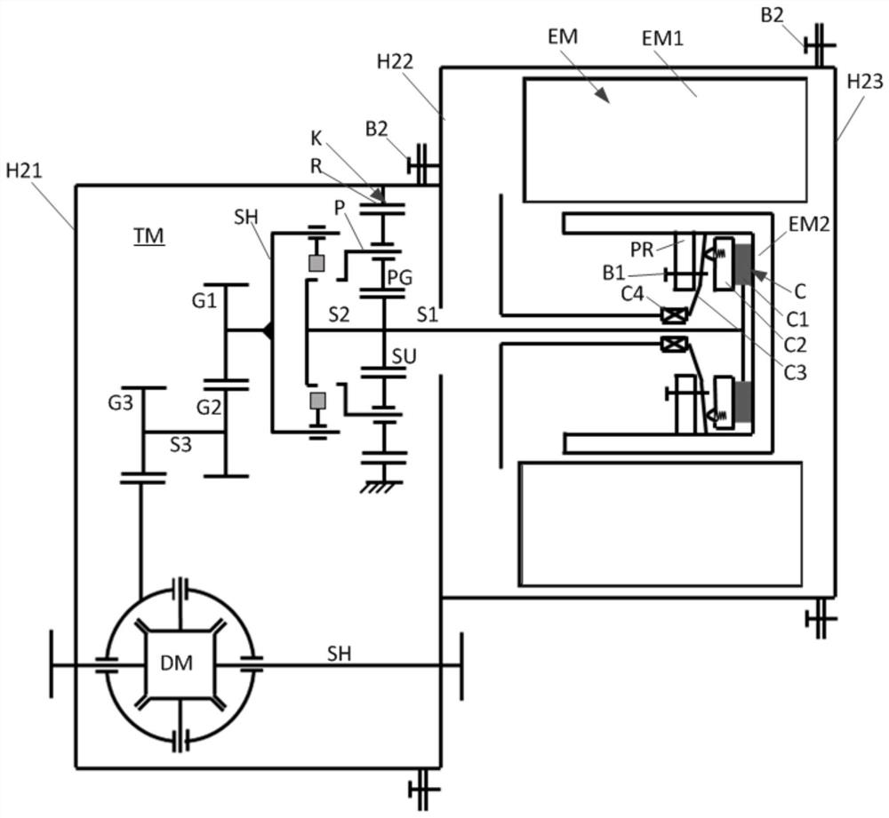
[0038] Such as figure 2 As shown, the electric bridge drive system for a vehicle according to an embodiment of the present invention includes an electric motor module (including an electric motor EM and a clutch C integrated togethe...
PUM
 Abstract
Description
Claims
Application Information