
Belt conveyor running state detection system based on line laser

A technology of belt conveyor and running status, which is applied in the direction of conveyor objects, conveyor control devices, transportation and packaging, etc. It can solve the problems of poor measurement accuracy, energy waste, equipment wear and other problems of electronic belt scales, and achieve easy integration Control, reduce types and quantities, and realize the effect of integrated control

Inactive Publication Date: 2021-01-12
SHANDONG UNIV OF SCI & TECH
View PDF2 Cites 9 Cited by
  • Summary
  • Abstract
  • Description
  • Claims
  • Application Information

AI Technical Summary

Problems solved by technology

At the same time, it can be used to start the conveyor along the coal flow, but most of the belt conveyors in coal mines are running at a constant speed after starting, no matter how much the load on the conveyor belt is
At the same time, in the transportation system composed of multi-stage conveyors, the starting method of "starting against the coal flow" also caused unnecessary energy waste and equipment wear and tear. At present, the monitoring means for the load is mainly the electronic belt scale. The contact of the conveyor belt converts the pressure signal into an electrical signal, and then calculates the reverse load. Because of the tension of the conveyor belt, when the load is different, the contact degree between the conveyor belt and the belt scale is different. Therefore, the electronic belt scale poor measurement accuracy
[0004] There are many reasons for the deviation of the conveyor belt, which can be summarized as: deviation caused by installation accuracy; deviation caused by machining accuracy, deviation caused by misalignment of material loading; current deviation detection mainly relies on deviation sensor, and its basic principle is similar Due to the limit switch, the visualization of deviation data cannot be realized

Method used


Image

  • Belt conveyor running state detection system based on line laser
  • Belt conveyor running state detection system based on line laser
  • Belt conveyor running state detection system based on line laser

Examples


Embodiment Construction

[0022] The following will clearly and completely describe the technical solutions in the embodiments of the present invention with reference to the accompanying drawings in the embodiments of the present invention. Obviously, the described embodiments are only some, not all, embodiments of the present invention. Based on the embodiments of the present invention, all other embodiments obtained by persons of ordinary skill in the art without making creative efforts belong to the protection scope of the present invention.

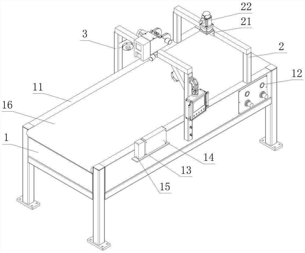
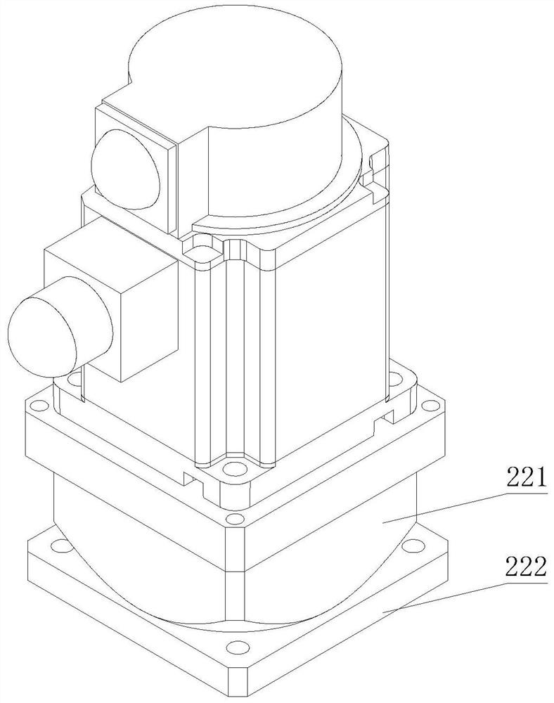
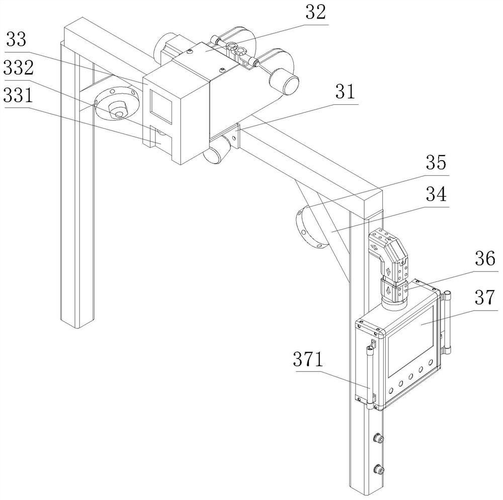
[0023] see figure 1 and Figure 4 , a belt conveyor operating state detection system based on line laser, including a conveyor body 1, the upper end of the conveyor body 1 is fixedly connected with a side plate 11, and the upper surface of one end of the side plate 11 is fixedly connected with a first bracket 2. The first bracket 2 is used to install the first camera 22. The side panel 11 below the first bracket 2 is equipped with a control panel 12. The cont...


PUM


Abstract

The invention discloses a belt conveyor running state detection system based on line laser. The belt conveyor running state detection system comprises a conveyor body, a first bracket is fixedly connected to the upper surface of one end of a side edge plate, a second supporting plate is mounted on one side of the upper end of the first bracket, a first camera is mounted on the second supporting plate, a third supporting plate is installed on one side of the upper end of a second bracket, a second camera is installed on the upper surface of the third supporting plate, and a laser emitter is installed on one side of the second camera. According to the belt conveyor running state detection system based on the line laser, the laser emitter emits two perpendicular light to form different material forms, so that the first camera obtains a smooth and continuous curve or a discrete non-smooth line segment of the surface of a material, through different image processing methods in combination with the material moving time and camera frame rate, the volume of the material is calculated; and a conveyor operation image is obtained through the second camera, and the edge information of a conveyor belt is obtained through an image processing algorithm.

Description

technical field [0001] The invention relates to the technical field of belt conveyors, in particular to a belt conveyor operating state detection system based on line laser. Background technique [0002] With the needs of Industry 4.0 and smart mine construction, belt conveyors, as one of the most important transportation equipment in the field of continuous transportation of bulk materials, are currently developing towards intelligence and integration. At present, most of the eight protections used in belt conveyors in coal mines use various types of sensors for state detection, such as deviation sensors, tear sensors, coal pile sensors, etc. First, there are a large number of sensors, and secondly, there are various types of sensors. There are various principles and forms, it is difficult to realize integrated management, and it is difficult to quantitatively describe the operation status of the belt conveyor, which does not meet the needs of the highly intelligent and aut...

Claims


Application Information

Patent Timeline
Patent Type & Authority Applications(China)
IPC IPC(8): B65G43/02
CPCB65G43/02
Inventor 张梦超周满山石浩张媛于岩
Owner SHANDONG UNIV OF SCI & TECH
Learn More