[0023] The following will clearly and completely describe the technical solutions in the embodiments of the present invention with reference to the accompanying drawings in the embodiments of the present invention. Obviously, the described embodiments are only some, not all, embodiments of the present invention. The following description of at least one exemplary embodiment is merely illustrative in nature and in no way taken as limiting the invention, its application or uses. Based on the embodiments of the present invention, all other embodiments obtained by persons of ordinary skill in the art without creative efforts fall within the protection scope of the present invention.
[0024] It should be noted that the terminology used here is only for describing specific implementations, and is not intended to limit the exemplary implementations according to the present application. As used herein, unless the context clearly dictates otherwise, the singular is intended to include the plural, and it should also be understood that when the terms "comprising" and/or "comprising" are used in this specification, they mean There are features, steps, operations, means, components and/or combinations thereof.
[0025] The relative arrangements of components and steps, numerical expressions and numerical values set forth in these embodiments do not limit the scope of the present invention unless specifically stated otherwise. At the same time, it should be understood that, for the convenience of description, the sizes of the various parts shown in the drawings are not drawn according to the actual proportional relationship. Techniques, methods and devices known to those of ordinary skill in the relevant art may not be discussed in detail, but where appropriate, such techniques, methods and devices should be considered part of the Authorized Specification. In all examples shown and discussed herein, any specific values should be construed as illustrative only, and not as limiting. Therefore, other examples of the exemplary embodiment may have different values. It should be noted that like numerals and letters denote like items in the following figures, therefore, once an item is defined in one figure, it does not require further discussion in subsequent figures.
[0026] In the description of the present invention, it should be understood that orientation words such as "front, back, up, down, left, right", "horizontal, vertical, vertical, horizontal" and "top, bottom" etc. indicate the orientation Or positional relationship is generally based on the orientation or positional relationship shown in the drawings, and is only for the convenience of describing the present invention and simplifying the description. In the absence of a contrary description, these orientation words do not indicate or imply the device or element referred to. It must have a specific orientation or be constructed and operated in a specific orientation, so it should not be construed as limiting the protection scope of the present invention; the orientation words "inner and outer" refer to the inner and outer relative to the outline of each component itself.
[0027] For the convenience of description, spatially relative terms may be used here, such as "on ...", "over ...", "on the surface of ...", "above", etc., to describe the The spatial positional relationship between one device or feature shown and other devices or features. It will be understood that the spatially relative terms are intended to encompass different orientations of the device in use or operation in addition to the orientation depicted in the figures. For example, if the device in the figures is turned over, devices described as "above" or "above" other devices or configurations would then be oriented "beneath" or "above" the other devices or configurations. under other devices or configurations". Thus, the exemplary term "above" can encompass both an orientation of "above" and "beneath". The device may be otherwise oriented (rotated 90 degrees or at other orientations) and the spatially relative descriptions used herein interpreted accordingly.
[0028] In addition, it should be noted that the use of words such as "first" and "second" to define components is only for the convenience of distinguishing corresponding components. To limit the protection scope of the present invention.
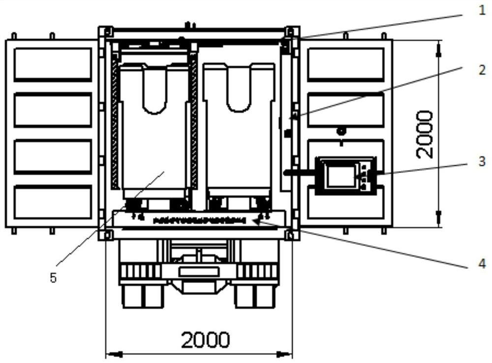
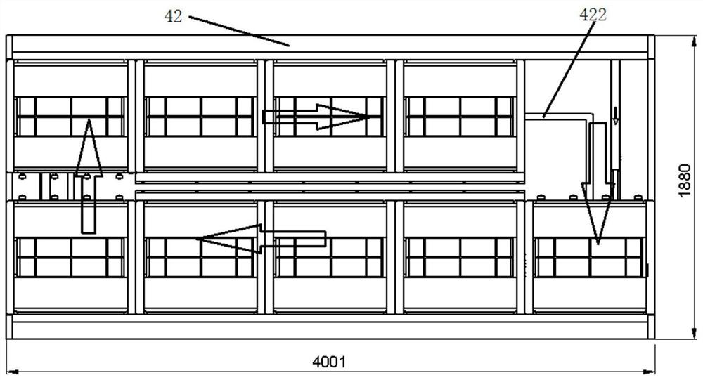
[0029] like Figure 1-4As shown, the present invention provides a cycle loading and unloading equipment, which is suitable for box-type trucks, such as JMC Shunda wide-body 129-horsepower 4.07-meter single-row van light trucks on the market or other brands of vehicles similar to this car body. But it is not limited to trucks with the above dimensions. The circulation loading and unloading equipment provided by this application can be adjusted in size to suit other models on the market. The circulation loading and unloading equipment provided by this application includes: manipulator 1, electrical cabinet 2, control box 3, control system and bottom Circular loading and unloading mechanism 4, manipulator 1 and electrical cabinet 2 are installed inside the compartment, of which the electrical cabinet 2 is ultra-thin to release the largest storage space in the compartment. The electrical cabinet 2 is equipped with the main power supply and control system, and the control box 3 Installed on the rear side door of the compartment, the control box 3 is provided with a control panel, which is electrically connected to the main power supply and the control system respectively, and the control system is used to find the empty storage level on the bottom circulation pick-and-discharge mechanism 4 and control the empty storage level. The storage level moves to the input position, and the manipulator 1 is controlled to grab the material box 5 and place it on the empty storage level and memorize the position of the material box 5 or control the specified storage level to move to the output level according to the set distribution requirements. Control the manipulator 1 to grab the corresponding material box 5 for distribution, and the manipulator 1 is used to grab the material box 5 outside the vehicle and place it on the feed position of the bottom cycle feeding mechanism 4 or grab the material box 5 from the discharge position and place it To the outside of the car, specifically, the bottom circulation take-and-discharge mechanism 4 is used for the sorting and random pick-and-place of the material box 5, and the bottom circulation take-and-discharge mechanism 4 includes a plurality of cyclically moving storage positions, a guide base 42 and a bottom power Servo mechanism, the bottom power servo mechanism drives the storage level to move on the guide base 42 in a certain order, and the storage level moves to the feed position or discharge position in a cycle under the control of the control system. In this embodiment, the storage position The bits move on the guide base 42 in a clockwise circular manner. This system is mainly to automatically place the material box 5 containing hotel towels and other materials into the compartment and quickly find and take it out. When feeding, just push the material box 5 to the designated position, and manually press the enter The material start button, the bottom circular pick-and-discharge mechanism 4 will automatically search for the empty storage level and move the empty storage level to the feeding position, the manipulator 1 will pick up the material box 5 and place it on the feeding position, and the control system will automatically memorize the position. When the position of the material box 5 needs to be dispatched, the personnel only need to find the loaded goods through the corresponding touch screen, and click the pick-up button, and the bottom circular pick-and-discharge mechanism 4 will automatically transport the corresponding material box 5 to The discharge position, and then the manipulator 1 takes out the material box 5 from the discharge position, and places it on the corresponding position on the ground, that is, the operation is completed. This application uses the bottom circulation feeding and discharging mechanism 4, which can solve the problem of manually sorting materials and finding materials Work, this application adopts an intelligent control system, which can solve the problem of the hotel distribution order of materials, and the materials can be picked and placed arbitrarily without restrictions; the use of manipulator 1 for intelligent retrieving is easy to operate, and can be used with simple training, which solves the problem The problems of low efficiency and high strength caused by manual handling improve the efficiency of material handling and search, and save labor costs.
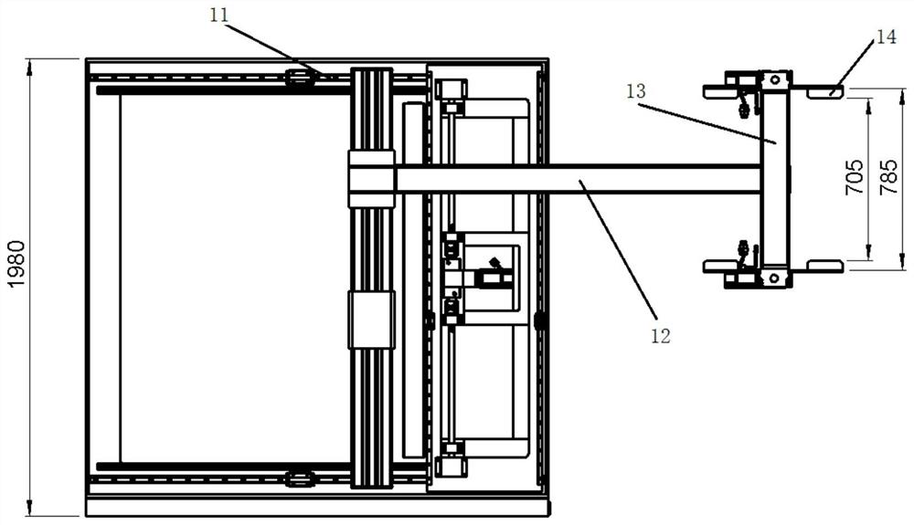
[0030] According to an embodiment of the present application, the manipulator 1 includes an X-axis servo module 11, a Y-axis servo module 12, a Z-axis servo module 13 and a grasping mechanism 14, and the X-axis servo module 11 drives the grasping mechanism 14 along the X axis. Axial movement, the Y-axis servo module 12 drives the grabbing mechanism 14 to move along the Y-axis, and the Z-axis servo module 13 drives the grabbing mechanism 14 to move along the Z-axis. In this embodiment, the X-axis servo module 11, Both the Y-axis servo module 12 and the Z-axis servo module 13 are composed of a servo motor and a ball screw. The servo motor in each servo module drives the nut to move along the screw. The X-axis servo module 11 is installed in the carriage The top of the top, the Y-axis servo module 12 is connected with the X-axis servo module 11, the Z-axis servo module 13 is connected with the Y-axis servo module 12, the grabbing mechanism 14 is connected with the Z-axis servo module 13, and the X-axis servo module Group 11, Y-axis servo module 12 and Z-axis servo module 13 drive the grabbing mechanism 14 to move along the X, Y, and Z directions to the feed position or the discharge position to grab the material box 5, which needs to be explained What is more important is that the material feed position and the material discharge position are located at the outermost side of the compartment. This setting is convenient for the manipulator 1 to pick and place the goods. The material discharge position and the material feed position can be at the same position or different. It is set side by side with the discharge position at the entrance of the carriage, and the two are not in the same position.
[0031] According to an embodiment of the present application, the bottom circulation loading and unloading mechanism 4 in the present application has 9 storage positions, and the quantity of the storage positions can be correspondingly changed according to the length and the truck type. Specifically, each storage position is composed of A sliding base 41 is formed. The sliding base 41 is mainly used to carry the tooling and the material box 5. It has the characteristics of four-way movement. Its structural form is mainly composed of load-bearing wheels 412 and guide wheels 411. Through a reasonable structural form, it cooperates with the pedestal on the base. The guide rail 421 and the guide groove 422, driven by the power structure at the bottom, carry out logical movement. Specifically, the bottom of the sliding base 41 is provided with a load-bearing wheel 412 and a guide wheel 411, and the guide base 42 is provided with a guide rail 421 and a guide groove 422. The guide wheel 411 is slidably matched with the guide groove 422, and the load-bearing wheels 412 are evenly distributed on both sides of the guide rail 421 to cooperate with the guide rail 421 to realize motion bearing. The material level continuously passes through the input level and the output level. After passing through the required material level, the material box 5 stops at this station and waits for the next operation. Preferably, the sliding base 41 is provided with a positioning tool 413 to Ensure that the material box 5 does not turn over during transportation.
[0032] According to one embodiment of the application, the control box 3 is installed on the rear side door on the same side as the discharge position. In this embodiment, the control box 3 and the discharge position are all arranged on the right side of the compartment, which is convenient for users to operate And control, when the door is closed, the right side is the discharge position, which happens to be an empty space, which can release space for the control box 3 to use.
[0033] It should be noted that the control system can be implemented in any suitable manner. For example, the control system can take the form of a microprocessor or a processor and a computer-readable device that stores computer-readable program codes such as software or firmware that can be executed by the microprocessor. Medium, logic gates, switches, Application Specific Integrated Circuit, ASIC, programmable logic controller and embedded microcontroller form. Those skilled in the art also know that, in addition to realizing the control system in a purely computer-readable program code mode, it is entirely possible to make the control system use logic gates, switches, application-specific integrated circuits, programmable logic control systems, and embedded The same function can be realized in the form of micro-control system and so on. Therefore, such a control system can be regarded as a hardware component, and the devices included in it for realizing various functions can also be regarded as structures within the hardware component. Or even, means for realizing various functions can be regarded as a structure within both a software module realizing a method and a hardware component.
[0034] Specific working process:
[0035] When loading materials, the worker pushes the special material box 5 to the designated position at the entrance of the truck, manually presses the start button on the control panel to start the equipment, and the bottom circulation loading and unloading mechanism 4 automatically finds the empty storage level and controls the empty storage level Move to the feeding position, the manipulator 1 automatically grips the material box 5 and places it at the empty storage position, and the bottom circulation feeding and discharging mechanism 4 searches for the empty storage position and enters the loading state to be loaded, and the system automatically memorizes the number of the material box 5 ( Generally set as the hotel name) and storage address and other information, reciprocating, until the material box 5 is loaded;
[0036] When distributing, manually search for the number of the material box 5 to be taken out from the display screen of the control panel, click to take it out, and the bottom circular feeding mechanism 4 will automatically move the material box 5 to the discharge position, and the manipulator 1 will pick it up and place it on the ground. The cycle repeats until the unloading of the hotel materials is completed, and the program stops.
[0037] The circular loading and unloading equipment provided by this application can solve the work of manually sorting and searching materials by using the bottom circular loading and unloading mechanism 4; adopting an intelligent control system can solve the problem of the hotel distribution order of materials, and the distribution of materials can be realized Arbitrary pick and place, unlimited; use the robot arm 1 to carry out intelligent retrieving, easy to operate, and can be used with simple training, which solves the problems of low efficiency and high strength caused by manual handling, and improves the efficiency of material handling and search. Save labor cost.
[0038] The above is only a preferred embodiment of the present invention, but the scope of protection of the present invention is not limited thereto. Anyone familiar with the technical field within the technical scope disclosed in the present invention, according to the technical solutions of the present invention and its Any equivalent replacement or change of the inventive concept shall fall within the protection scope of the present invention.