Finned heat exchanger

A fin-type heat exchanger and a casing technology are applied in the field of fin-type heat exchangers, which can solve the problems of small heat exchange area and low heat exchange efficiency of fin-type heat exchangers, and achieve a large heat exchange area, High heat exchange efficiency and the effect of improving heat exchange efficiency

Pending Publication Date: 2021-01-12
无锡帕捷科技有限公司
View PDF0 Cites 0 Cited by
  • Summary
  • Abstract
  • Description
  • Claims
  • Application Information

AI Technical Summary

Problems solved by technology

[0004] In view of the disadvantages of relatively low heat transfer efficiency and small heat transfer area of ​​the existing finned heat exchangers used in environmental test chambers, the applicant provides a finned heat exchanger with a reasonable structure. , In the case of small volume, it has high heat transfer efficiency and large heat transfer area

Method used


Image

  • Finned heat exchanger
  • Finned heat exchanger
  • Finned heat exchanger

Examples


Embodiment Construction

[0028] The specific implementation manner of the present invention will be described below in conjunction with the accompanying drawings.

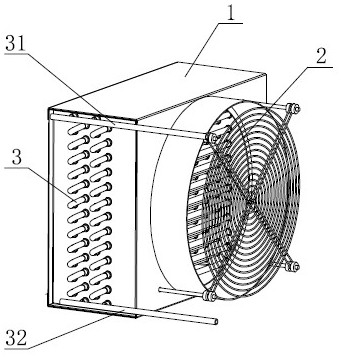
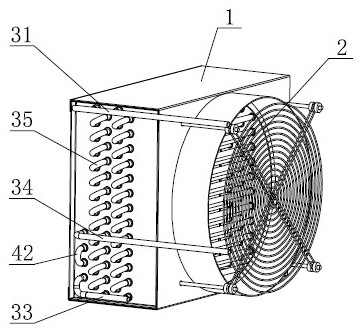
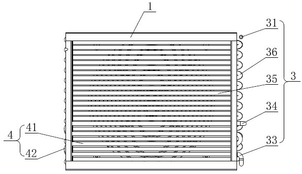
[0029] Such as figure 2 As shown, the front and rear sides of the square casing 1 of the present invention are open surfaces, the left and right sides and the upper and lower sides are closed surfaces, the front open surface of the casing 1 is an air suction port, and the rear side of the casing 1 is fixedly provided with a suction fan. 2. After the suction fan 2 is turned on, the cold air is sucked in from the front suction port of the casing 1 and discharged from the rear side of the casing 1. Such as figure 2 , Figure 4 , Figure 5 As shown, at least one set of refrigeration tube groups 3 are arranged inside the casing 1 from front to back. In this embodiment, two groups of refrigeration tube groups 3 are arranged in the casing 1 from front to back; A refrigerant inlet pipe 31 is provided at the upper end of the right side, and a...


PUM


Abstract

The invention discloses a finned heat exchanger. A suction fan is arranged on one side face of a housing, an air suction opening is formed in the other opposite side face of the housing, at least onerefrigerating pipe set is arranged in the housing, and a refrigerant inlet pipe and a first discharge pipe communicate with the refrigerating pipe sets respectively. One end of the first discharge pipe communicates with a drying filter of a refrigerating system, and the other end of the first discharge pipe communicates with a second discharge pipe through a circuitous pipe. According to the finned heat exchanger, the second discharge pipe is arranged on the first discharge pipe through the circuitous pipe, part of a liquid refrigerant in the first discharge pipe returns to the air suction opening of the housing through the circuitous pipe to conduct secondary heat exchange with cold air, and under the condition that the finned heat exchanger is low in power and small in size, the heat exchange path of the refrigerant is further prolonged through the circuitous pipe returning to the air suction opening, the larger heat exchange area is obtained, and the heat exchange efficiency is higher.

Description

technical field [0001] The invention relates to the technical field of heat exchangers, in particular to a finned heat exchanger applied to an environmental test chamber. Background technique [0002] Finned heat exchanger is the most widely used heat exchange equipment in gas and liquid heat exchangers. It is mainly used for air heating in drying systems. It is the main equipment in hot air devices. Install fins to achieve the purpose of enhancing heat transfer. [0003] Such as figure 1 Shown is an existing finned heat exchanger used in an environmental test chamber. A suction fan 2 is arranged on the rear side of the casing 1, and a cooling tube group 3 is arranged inside the casing 1. The cooling tube groups 3 are arranged in parallel and at intervals and communicate with each other. The outer circumference of the copper tube is provided with several fins along the radial direction; the gaseous refrigerant enters the refrigeration tube group 3 from the refrigerant inle...

Claims


Application Information

Patent Timeline
Patent Type & Authority Applications(China)
IPC IPC(8): F28D7/08F28F1/10
CPCF28D7/087F28F1/10
Inventor 范洪峰顾亚栋代明然
Owner 无锡帕捷科技有限公司
Why Eureka
Try Eureka