
Rigid cylinder vortex-induced vibration test device

A vortex-induced vibration and test device technology, applied in the field of ocean engineering, can solve problems such as tube fatigue damage, inflexible adjustment, and environmental pollution, and achieve the effects of reducing interference resistance, improving test efficiency, and improving test accuracy

Pending Publication Date: 2021-01-12
SHENZHEN GRADUATE SCHOOL TSINGHUA UNIV
View PDF2 Cites 1 Cited by
  • Summary
  • Abstract
  • Description
  • Claims
  • Application Information

AI Technical Summary

Problems solved by technology

When the vortex-induced vibration acts on the tube for a long time, it will cause the fatigue damage of the tube, and the stress concentration damage may also occur in the short term, resulting in huge economic losses and environmental pollution.
There are various research methods for this, such as numerical simulation, model test and theoretical research, but numerical simulation requires a lot of computing resources, so model test has become an applicable and reliable research method
Chinese patent documents CN 102331332 A and CN 111089697A disclose a cylindrical vortex-induced vibration device with controllable vibration degrees of freedom. The main defects are: 1) the adjustment of system stiffness (spring type, number, etc.) is not flexible enough; 2) After the whole device is placed in water, the resistance of the shelf is relatively large, which affects the vibration of the cylinder; 3) Since the device for pulling the test cylinder is in a vertical plane, it may be stuck during the experiment, making the experiment impossible

Method used


Image

  • Rigid cylinder vortex-induced vibration test device
  • Rigid cylinder vortex-induced vibration test device
  • Rigid cylinder vortex-induced vibration test device

Examples


Embodiment Construction

[0028] In order to make the technical problems, technical solutions and beneficial effects to be solved by the embodiments of the present invention clearer, the present invention will be further described in detail below in conjunction with the accompanying drawings and embodiments. It should be understood that the specific embodiments described here are only used to explain the present invention, not to limit the present invention.

[0029] It should be noted that when an element is referred to as being “fixed” or “disposed on” another element, it may be directly on the other element or be indirectly on the other element. When an element is referred to as being "connected to" another element, it can be directly connected to the other element or indirectly connected to the other element. In addition, the connection can be used for both fixing function and circuit communication function.

[0030] It is to be understood that the terms "length", "width", "top", "bottom", "front"...


PUM


Abstract

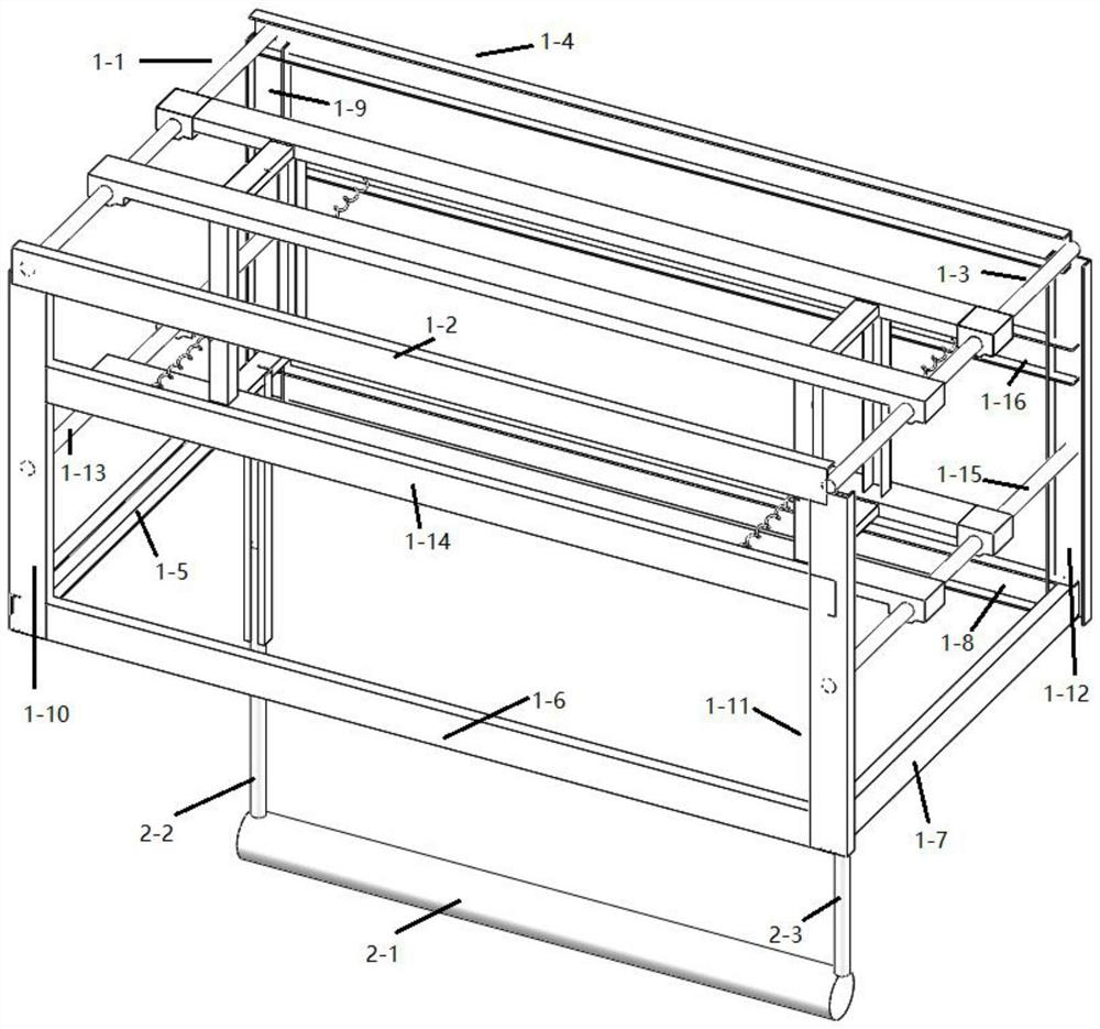
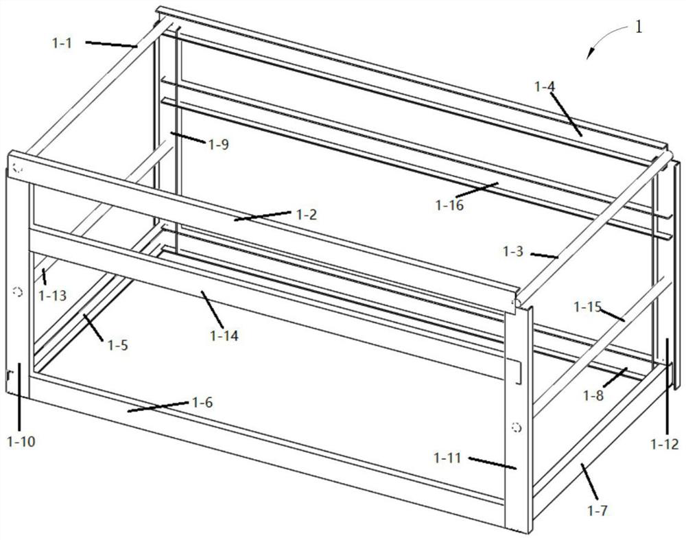
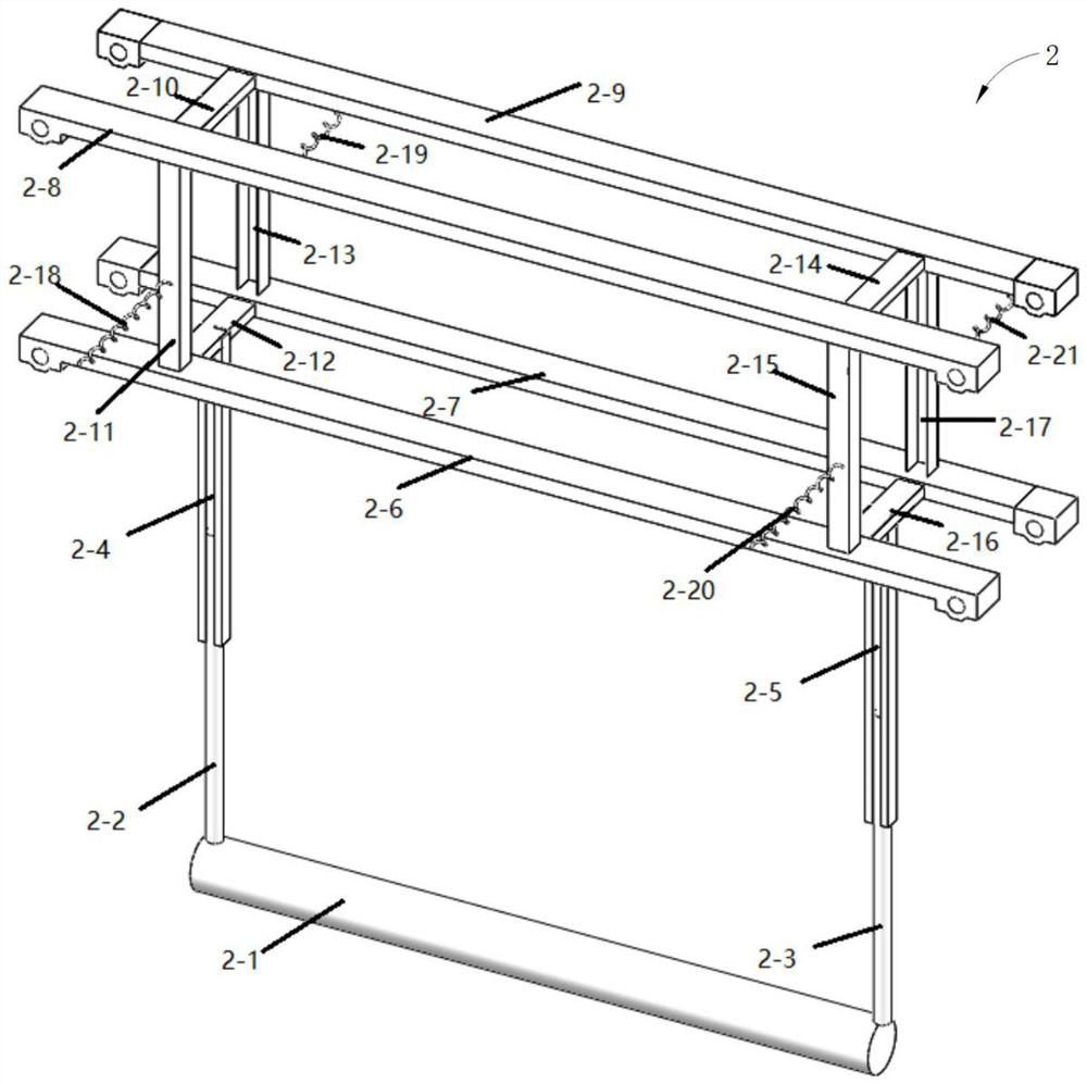
The invention discloses a rigid cylinder vortex-induced vibration test device which comprises an outer fixing frame, an inner rigid supporting assembly and an experimental cylinder, the outer fixing frame comprises a fixing frame body and a first set of sliding rails arranged in the water flow direction, and the first set of sliding rails are connected to the fixing frame body; the inner rigid supporting assembly comprises a movable rigid supporting frame, a second set of sliding rails, a first set of elastic pieces and a second set of elastic pieces, the movable rigid supporting frame is arranged perpendicular to the water flow direction, and the movable rigid supporting frame is movably connected to the first set of sliding rails; the first set of elastic pieces are arranged on the two sides of the movable rigid supporting frame in the water flow direction and connected with the fixing frame body, the second set of sliding rails are arranged in the vertical direction and connected with the movable rigid supporting frame, and the second set of elastic pieces are limited in the second set of sliding rails. The experimental cylinder is connected with the movable rigid support framethrough the second set of elastic pieces. According to the invention, the blocking phenomenon of the experimental rigid cylinder in the vortex-induced vibration test is solved.

Description

technical field [0001] The invention relates to the technical field of marine engineering, in particular to a rigid cylinder vortex-induced vibration test device. Background technique [0002] In recent years, in the development of offshore oil and gas resources, all kinds of equipment are inseparable from different types of cylinders, such as cylinders that make up marine umbilical cables and other connecting parts. When various bluff cylinders are placed in ocean currents, wake vortices will be generated due to the instability of the shear layer of the fluid. When the wake vortex frequency is within a certain range, it will cause the vibration of the pipe fittings. This phenomenon is called vortex induced vibration. When vortex-induced vibration acts on the tube for a long time, it will cause fatigue damage to the tube, and stress concentration damage may also occur in the short term, resulting in huge economic losses and environmental pollution. There are various resear...

Claims


Application Information

Patent Timeline
IPC IPC(8): G01M7/06G01M7/02
CPCG01M7/025G01M7/06
Inventor 冯云丽李孙伟陈道毅
Owner SHENZHEN GRADUATE SCHOOL TSINGHUA UNIV
Learn More