User preference-based dynamic computing migration method and device for smart city

A user and city technology, applied in the computer field, can solve problems such as not being able to meet the dynamic needs of users in smart cities

Active Publication Date: 2021-01-12
HUAQIAO UNIVERSITY
View PDF6 Cites 5 Cited by
  • Summary
  • Abstract
  • Description
  • Claims
  • Application Information

AI Technical Summary

Problems solved by technology

Although there are many optimization methods for computing migration in the MEC environment, these research methods may not meet the dynamic needs of users in smart cities

Method used


Image

  • User preference-based dynamic computing migration method and device for smart city
  • User preference-based dynamic computing migration method and device for smart city
  • User preference-based dynamic computing migration method and device for smart city

Examples


Embodiment 1

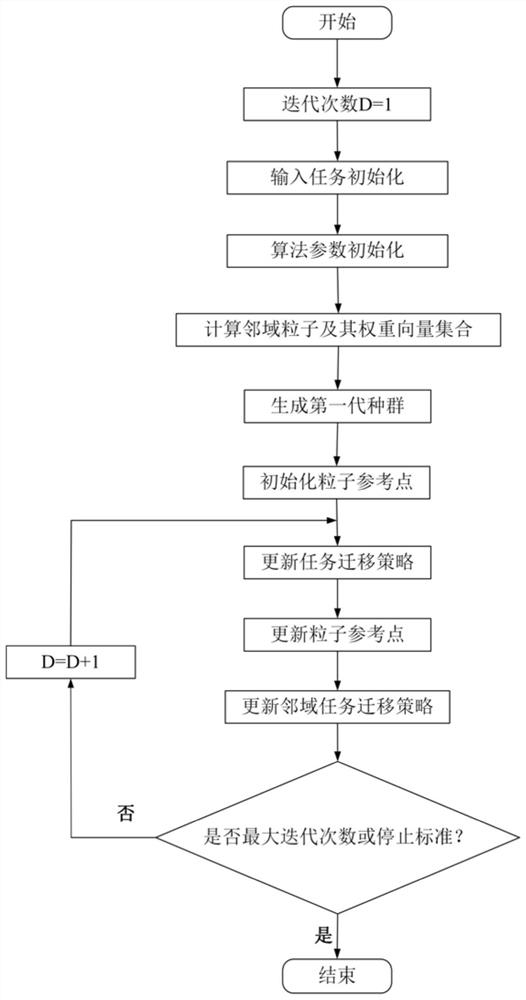
[0126] This embodiment provides a method, such as figure 1 shown, including the following steps:

[0127] Step 1: task initialization; define task input set as It={I 1 , I 2 ,...,I N}, where each I N is defined as a group; I N Each subtask in As an individual in the population, also known as a particle, it is defined as a binary array, and has where W t N is the amount of tasks to be processed by the tth particle in the Nth population, Indicates the task amount that the tth particle in the Nth population needs to transmit to the subsequent task; the elite group Each population in the elite group Both come from the initial task group It;

[0128] Step 2: Algorithm parameter initialization; the number of sub-problems that can be decomposed into P C , Algorithm stopping criterion D off , the maximum number of iterations of the population M, a set of uniform weight vectors H={λ 1 ,λ 2 ,...,λ N}, the number T of the neighborhood vector set of each particle; the...

Embodiment 2

[0154] In this embodiment, a device is provided, such as Figure 5 As shown, the following modules are included:

[0155] The task initial module defines the task input set as It={I 1 , I 2 ,...,I N}, where each I N is defined as a group; I N Each subtask in As an individual in the population, also known as a particle, it is defined as a binary array, and has where W t N is the amount of tasks to be processed by the tth particle in the Nth population, Indicates the task amount that the tth particle in the Nth population needs to transmit to the subsequent task; the elite group Each population in the elite group Both come from the initial task group It;

[0156] Parameter initialization module, the number of sub-problems that can be decomposed into P C , Algorithm stopping criterion D off , the maximum number of iterations of the population M, a set of uniform weight vectors H={λ 1 ,λ 2 ,...,λ N}, the number T of the neighborhood vector set of each particle...

Embodiment 3

[0184] This embodiment provides an electronic device, including a memory, a processor, and a computer program stored in the memory and operable on the processor. When the processor executes the computer program, any implementation manner in Embodiment 1 can be implemented.

[0185] Since the electronic device introduced in this embodiment is the device used to implement the method in Embodiment 1 of this application, based on the method described in Embodiment 1 of this application, those skilled in the art can understand the electronic device of this embodiment. Specific implementation methods and various variations thereof, so how the electronic device implements the method in the embodiment of the present application will not be described in detail here. As long as a person skilled in the art implements the equipment used by the method in the embodiment of the present application, it all belongs to the protection scope of the present application.


PUM


Abstract

The invention provides a user preference-based dynamic computing migration method and device for a smart city, and the method comprises the steps of initializing a set of input tasks; stipulating an algorithm stop standard, a population maximum iteration frequency, the number of neighborhood vector sets of each particle and a population initial migration strategy, and defining a group of weight vector sets required to be used in the algorithm; then, on the basis of an MOEA/D algorithm, continuously updating a migration strategy of the task by taking optimization of total energy consumption andtotal time delay of the mobile equipment task of the user side from generation to completion as a target; meanwhile, in order to meet the requirements of the user, adding an elitist strategy which can be changed in a directed mode according to the requirements and preferences of the user; according to the invention, an elitist strategy is adopted, energy consumption and time delay generated by task processing are comprehensively considered while user preferences are met, an appropriate calculation migration strategy is formulated for user tasks in an MEC environment, and the purpose of multi-objective optimization is achieved.

Description

technical field [0001] The present invention relates to the field of computer technology, in particular to a method and device for dynamic computing migration based on user preferences for smart cities. Background technique [0002] With the introduction and application of emerging concepts such as the Internet of Things and cloud computing, people's lives have undergone earth-shaking changes. At the same time, people's needs have further increased, especially in daily life cities. The result of modernization, get more novel and intelligent high-end services. Therefore, the traditional urban model may not be able to meet people's needs, or it may not be able to adapt to the development of modern society. To this end, people put forward the new concept of smart city, hoping to promote the modernization and intelligentization of the city through emerging information technologies such as the Internet of Things, and combine information technology with specific applications in t...

Claims


Application Information

Patent Timeline
Patent Type & Authority Applications(China)
IPC IPC(8): G06F9/48G06F9/50G06N3/00G06N3/12
CPCG06F9/4843G06F9/5088G06F9/5072G06N3/006G06N3/126Y02D10/00
Inventor 彭凯赵博海刘培琛
Owner HUAQIAO UNIVERSITY
Why Eureka
Try Eureka