
Power amplifier circuit

A power amplification circuit and amplifier technology, which is applied in the direction of power amplifiers, amplifier protection circuit layout, amplifiers, etc., can solve the problems of insufficient response speed and increased circuit size, and achieve the effect of suppressing breakdown

Pending Publication Date: 2021-01-12
MURATA MFG CO LTD
View PDF7 Cites 1 Cited by
  • Summary
  • Abstract
  • Description
  • Claims
  • Application Information

AI Technical Summary

Problems solved by technology

However, regarding the protection of amplifiers using control ICs, the speed of response to instantaneous overvoltage is not sufficient
In addition, since the protection function is given to the control IC, the size of the circuit increases

Method used


Image

  • Power amplifier circuit
  • Power amplifier circuit
  • Power amplifier circuit

Examples


Embodiment Construction

[0043] Hereinafter, embodiments of the present invention will be described in detail with reference to the drawings. In addition, the same code|symbol is attached|subjected to the same element, and repeated description is omitted as much as possible.

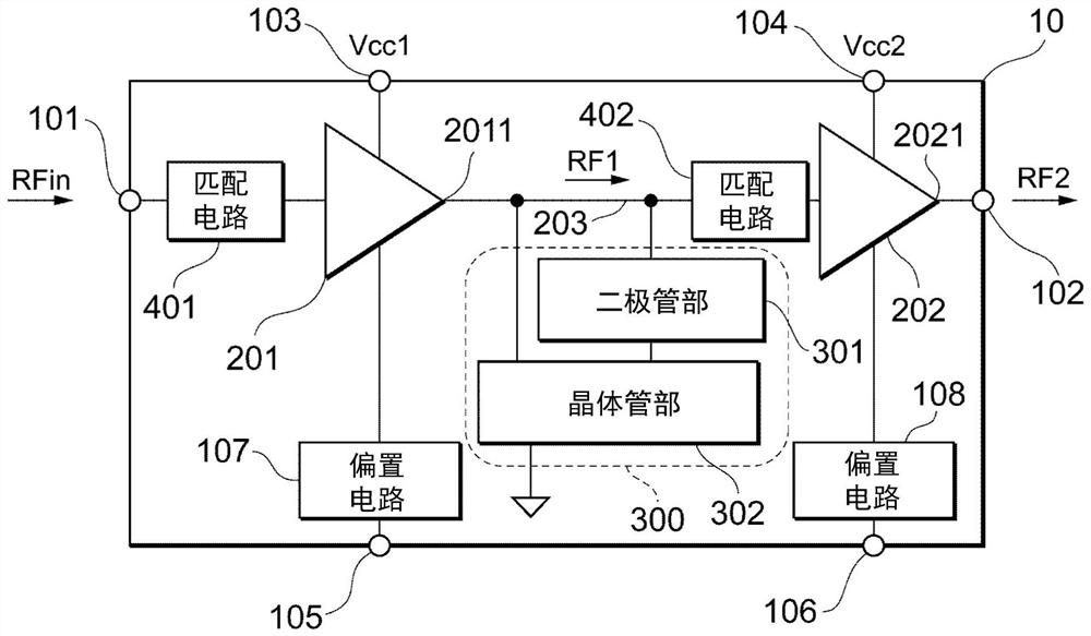
[0044] The power amplifying circuit 10 according to this embodiment will be described. exist figure 1 A block diagram of the power amplification circuit 10 is shown. Power amplifying circuit 10 has terminals 101 , 102 , 103 , 104 , 105 , 106 , bias circuits 107 , 108 , amplifiers 201 , 202 , signal line 203 , clamp circuit 300 , and matching circuits 401 , 402 .

[0045] Terminal 101 is connected to matching circuit 401 . An input signal RFin is supplied from the outside to the terminal 101 . The terminal 102 is connected to an output terminal 2021 of the amplifier 202 . The amplified signal RF2 is supplied from the terminal 102 to the outside.

[0046] The terminal 103 is connected to the amplifier 201 . The power supply...


PUM


Abstract

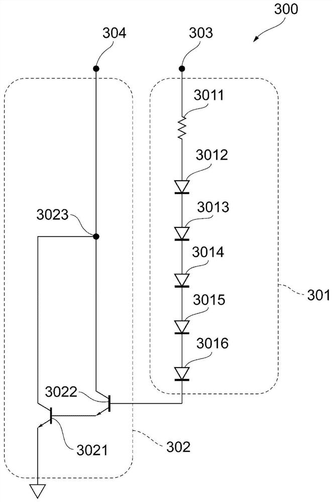
The invention provides a power amplifier circuit which suppresses the breakdown of an amplifier due to an excessive voltage. The power amplifier circuit (10) is provided with an amplifier (201) that amplifies an input signal (RFin) and outputs an amplified signal (RF1); an amplifier (202) that is provided at the post-stage of the amplifier (201), amplifies the amplified signal (RF1), and outputs an amplified signal (RF2); and a clamping circuit (300) that is provided between the signal line (203) between the amplifier (201) and the amplifier (202) and the ground, and suppresses the amplitude of the amplified signal (RF1).

Description

technical field [0001] The invention relates to a power amplifier circuit. Background technique [0002] In communication using a radio frequency (Radio Frequency: RF, radio frequency) signal of a mobile body such as a mobile phone, a power amplifier circuit is used to amplify the RF signal. Patent Document 1 discloses a semiconductor device provided with a protection circuit for preventing breakdown of the amplifier when an excessive voltage exceeding the allowable voltage is applied to the amplifier of the power amplifier circuit. By providing the protection circuit, it is possible to protect the circuit when an excessive voltage is applied from outside the power amplifier circuit. [0003] prior art literature [0004] patent documents [0005] Patent Document 1: Japanese Patent Laid-Open No. 2018-142688 [0006] In a power amplifier circuit, when multi-stage transistors are used for amplification, a higher voltage is applied to the amplifier in the subsequent stage t...

Claims


Application Information

Patent Timeline
Patent Type & Authority Applications(China)
IPC IPC(8): H03F1/52H03F3/21H03F3/68H03F3/19
CPCH03F1/52H03F3/211H03F3/68H03F3/19H03F2200/222H03F2200/387H03F2200/426H03F2200/451H03F2200/93H03F1/56H03F3/195H03F2200/444H03F1/0261H03F3/245H03F3/10H03F2200/441H03F3/21
Inventor 岛本健一
Owner MURATA MFG CO LTD
Learn More